Chopper stabilized amplifier

a stabilized amplifier and amplifier technology, applied in the direction of pulse automatic control, pulse technique, electronic switching, etc., can solve the problems of harmonic distortion in the output signal lpout(t), limited frequency characteristics, limited slew rate of operation amplifier circuit amp, etc., to reduce harmonic distortion and suppress glitching

Active Publication Date: 2012-08-21
OLYMPUS CORP
View PDF8 Cites 3 Cited by
  • Summary
  • Abstract
  • Description
  • Claims
  • Application Information

AI Technical Summary

Benefits of technology

[0032]The present invention provides a chopper stabilized amplifier that suppresses glitching that is generated because the operational amplifier circuit has limited frequency characteristics and a limited slew rate, and that makes it possible to obtain an output signal having less harmonic distortion.
[0042]According to the present invention, by performing analog conversion on the second modulated signal so as to convert it into an output signal using a demodulation signal having a waveform that corresponds to the differences between the frequency components of the first and second modulated signals, it is possible to suppress glitching that is generated because the operational amplifier circuit has limited frequency characteristics and a limited slew rate, and to obtain an output signal having less harmonic distortion.

Problems solved by technology

However, in actuality, the operational amplifier circuit AMP does have a limited slew rate and limited frequency characteristics.
Because the glitching generated in the output signal OUT(t) cannot be completely removed by a low-pass filter, it has the drawback that harmonic distortion is generated in the output signal LPOUT(t) after it has passed through the low-pass filter.

Method used


Image

  • Chopper stabilized amplifier
  • Chopper stabilized amplifier
  • Chopper stabilized amplifier

Examples


first preferred embodiment

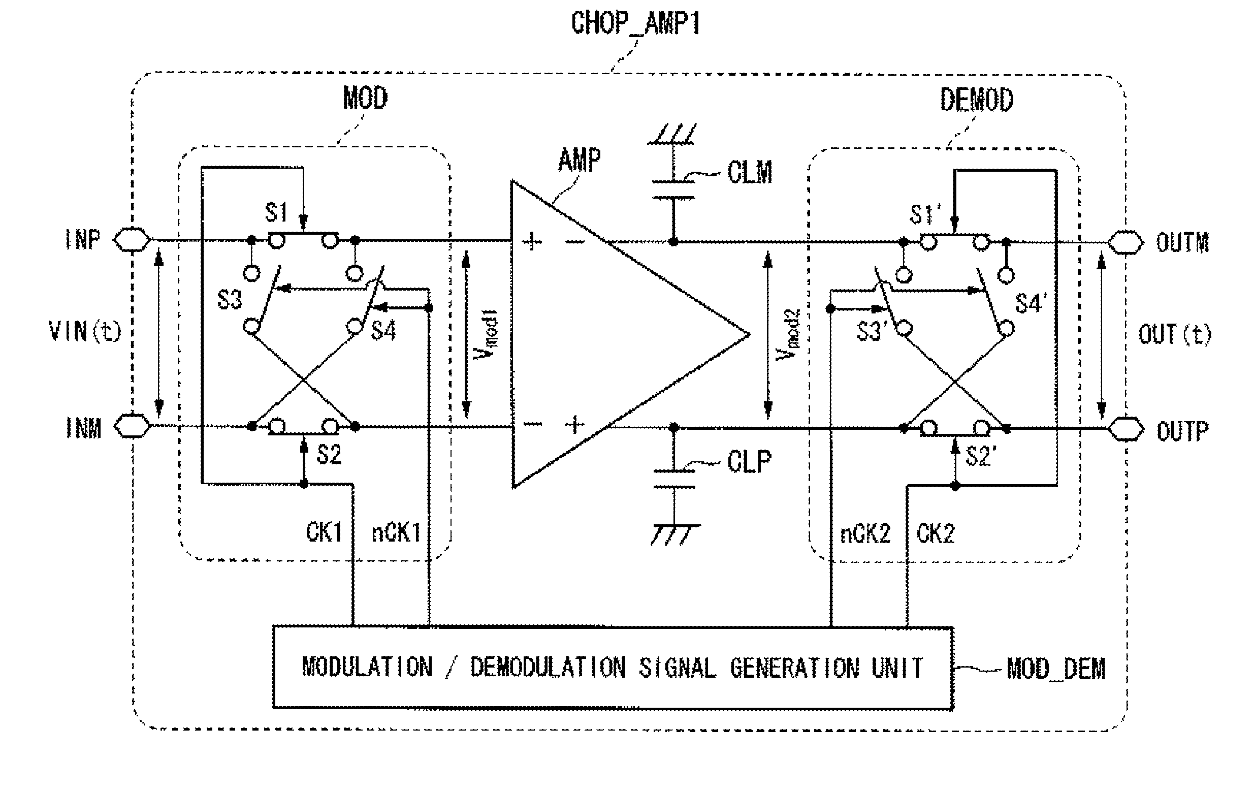
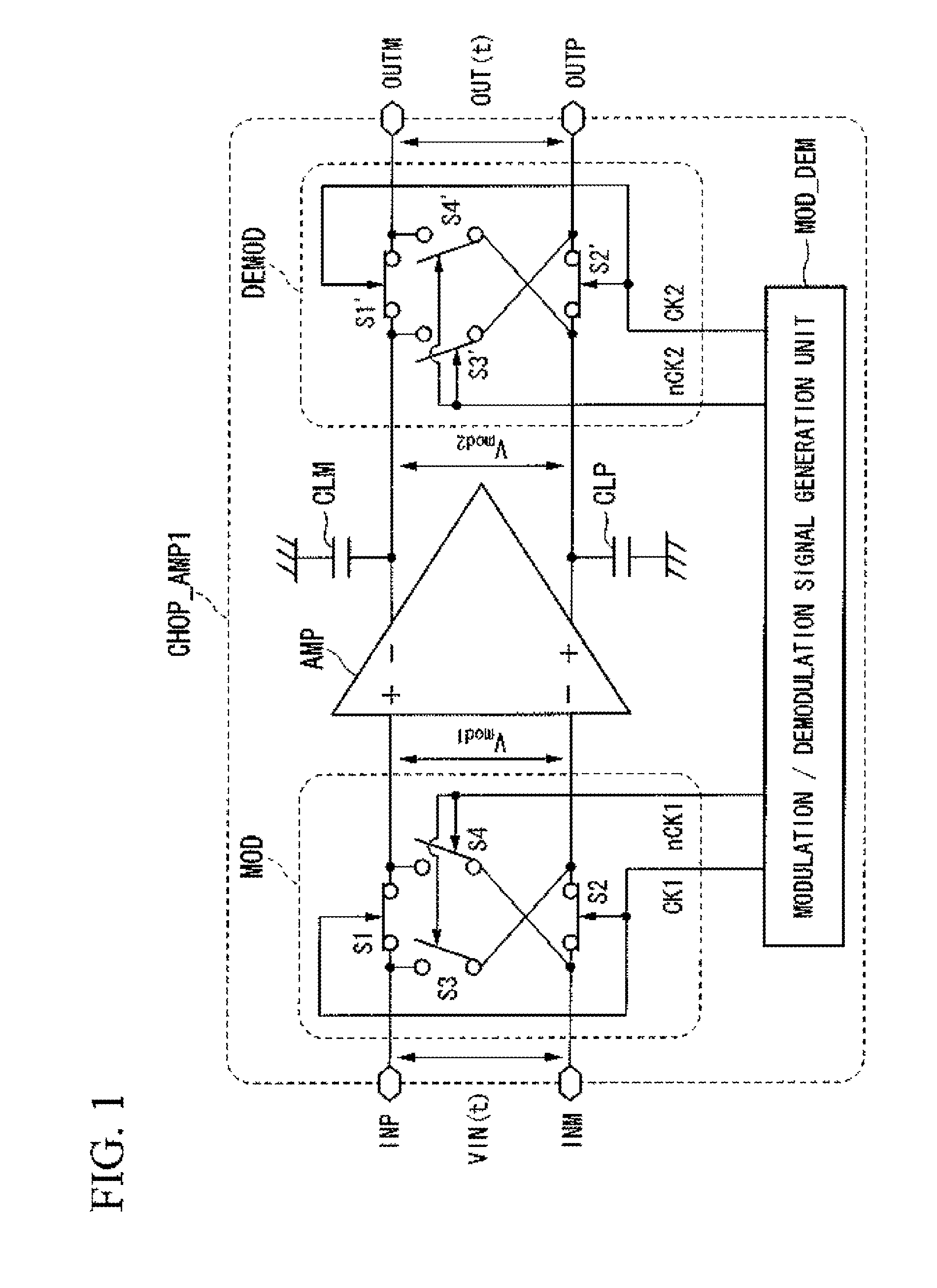
[0058]Firstly, a first preferred embodiment of the present invention will be described. The structure of a chopper stabilized amplifier in accordance with the first preferred embodiment will now be described using FIG. 1. FIG. 1 is a circuit diagram illustrating a structure of a chopper stabilized amplifier in accordance with the first preferred embodiment of the present invention. In FIG. 1, units that are the same as in the conventional chopper stabilized amplifier CHOP_AMP shown in FIG. 10 are given the same descriptive symbols and a description thereof is omitted.

[0059]A chopper stabilized amplifier CHOP_AMP 1 shown in FIG. 1 differs from a conventional chopper stabilized amplifier in that a modulation / demodulation signal generation unit MOD_DEM is provided that supplies modulation signals CK1 and modulation signals nCK1 to a modulation circuit MOD, and supplies demodulation signals CK2 and demodulation signals nCK2 to a demodulation circuit DEMOD.

[0060]Hereinafter, the modulati...

second preferred embodiment

[0068]Next, a second preferred embodiment of the present invention will be described. The structure of a chopper stabilized amplifier in accordance with the second preferred embodiment will now be described using FIG. 4. FIG. 4 is a circuit diagram illustrating the structure of a chopper stabilized amplifier in accordance with the second preferred embodiment of the present invention. In FIG. 4, units that are the same as in the chopper stabilized amplifier CHOP_AMP 1 in accordance with the first preferred embodiment which is shown in FIG. 1 are given the same descriptive symbols and a description thereof is omitted.

[0069]A chopper stabilized amplifier CHOP_AMP 2 shown in FIG. 4 differs from the chopper stabilized amplifier CHOP_AMP 1 of the first preferred embodiment in that the switch units S1 to S4 and the switch units S1′ to S4′ are replaced specifically with the respective NMOS transistors M1 to M4 and the NMOS transistors M1′ to M4′, and in that the internal structure of the mo...

third preferred embodiment

[0081]Next, a third preferred embodiment of the present invention will be described. The structure of a chopper stabilized amplifier according to the third preferred embodiment will now be described using FIG. 6. FIG. 6 is a circuit diagram illustrating the specific structure of a low-pass filter LP which forms part of the chopper stabilized amplifier CHOP_AMP 2 shown in FIG. 4.

[0082]The low-pass filter LP includes an operational amplifier circuit AMP′ in which a non-inverting input terminal is connected to the wiring of the modulation signal CK1, an inverting input terminal is connected to the wiring of the modulation signal nCK1, an inverting output terminal is connected to the wiring of the demodulation signal nCK2, and a non-inverting output terminal is connected to the wiring of the modulation circuit CK2.

[0083]The characteristics of the operational amplifier circuit AMP′ which is used as a low-pass filter are desirably the same as the characteristics of the operational amplifi...


PUM


Abstract

A chopper stabilized amplifier may include a modulation circuit that performs a digital conversion on an input signal so as to convert the input signal into a first modulated signal by using a modulation signal, the modulation signal being a rectangular wave having a predetermined frequency, an operational amplifier circuit that amplifies the first modulated signal so as to convert the first modulated signal into a second modulated signal, and a demodulation circuit that performs analog conversion on the second modulated signal so as to convert the second modulated signal into an output signal by using a demodulation signal, the demodulation signal having a waveform that corresponds to the differences between frequency components of the first modulated signal and the second modulated signal.

Description

BACKGROUND OF THE INVENTION[0001]1. Field of the Invention[0002]The present invention relates to a chopper stabilized amplifier.[0003]Priority is claimed on Japanese Patent Application No. 2010-195764, filed Sep. 1, 2010, the content of which is incorporated herein by reference.[0004]2. Description of the Related Art[0005]All patents, patent applications, patent publications, scientific articles, and the like, which will hereinafter be cited or identified in the present application, will hereby be incorporated by reference in their entirety in order to describe more fully the state of the art to which the present invention pertains.[0006]Chopper stabilized amplifiers are widely used as low-noise, low-drift direct-current amplifiers (see, for example, Japanese Unexamined Patent Application, First Publication No. S61-89704). The structure of a conventional chopper stabilized amplifier will now be described using FIG. 10. FIG. 10 is a circuit diagram illustrating the structure of a con...

Claims


Application Information

Patent Timeline
Patent Type & Authority Patents(United States)
IPC IPC(8): H03F1/02
CPCH03F3/45475H03F3/387
Inventor OSAWA, MASATO
Owner OLYMPUS CORP
Why Eureka
Try Eureka