

Electronic component having a movable louver
a technology of electronic components and louvers, which is applied in the direction of electrical apparatus casings/cabinets/drawers, process and machine control, instruments, etc., can solve the problems of components receiving an over-abundance of airflow, fans typically consume more electricity than are necessary, and the heat dissipation of electronic components during their operation is relatively larg
- Summary
- Abstract
- Description
- Claims
- Application Information
AI Technical Summary
Benefits of technology
Problems solved by technology
Method used
Image

Examples
Embodiment Construction
[0008]For simplicity and illustrative purposes, the present invention is described by referring mainly to exemplary embodiments. In the following description, numerous specific details are set forth to provide a thorough understanding of the embodiments. However, it will be apparent to one of ordinary skill in the art that the present invention may be practiced without limitation to these specific details. In other instances, well known methods and structures have not been described in detail to avoid unnecessarily obscuring the description of the embodiments.
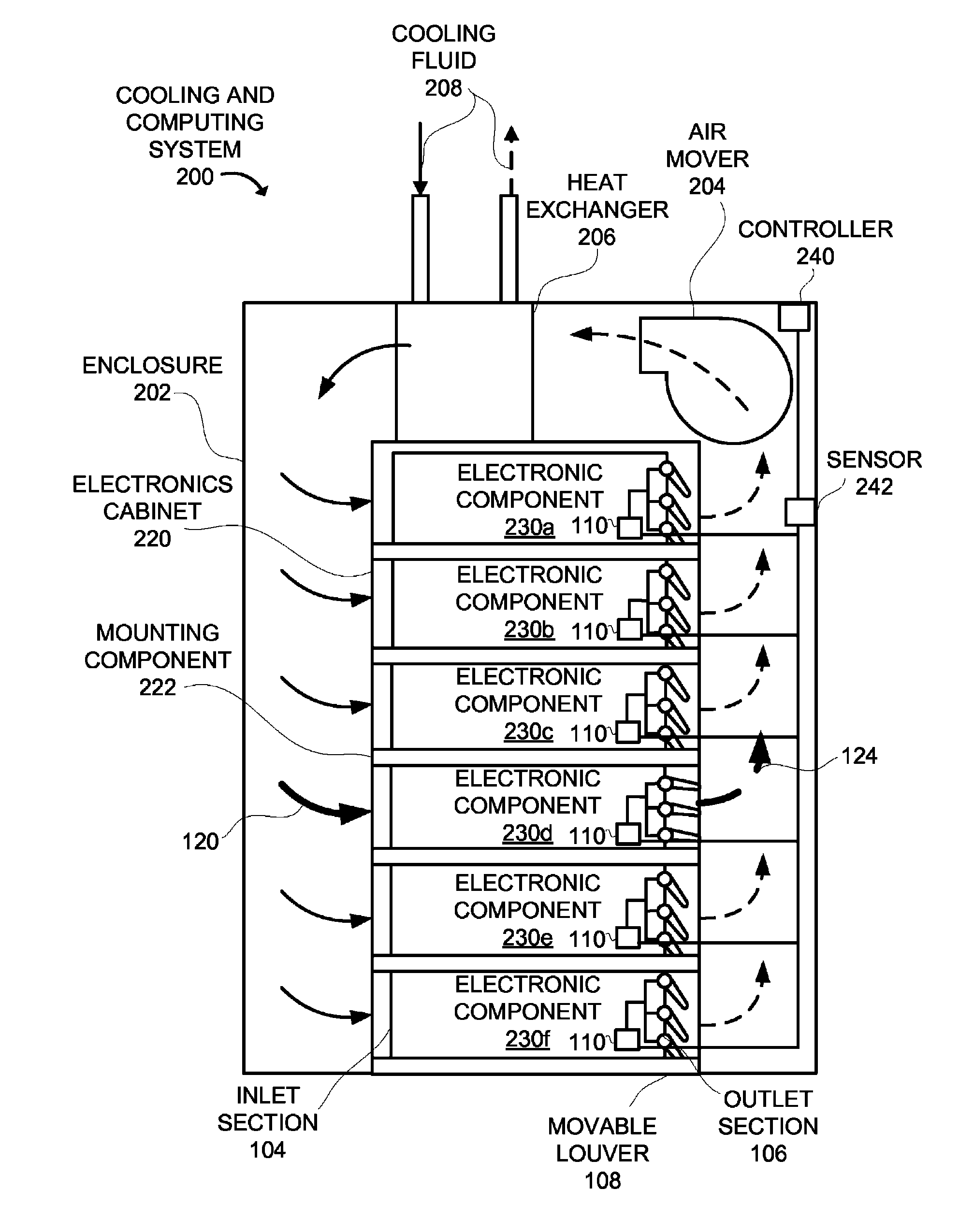
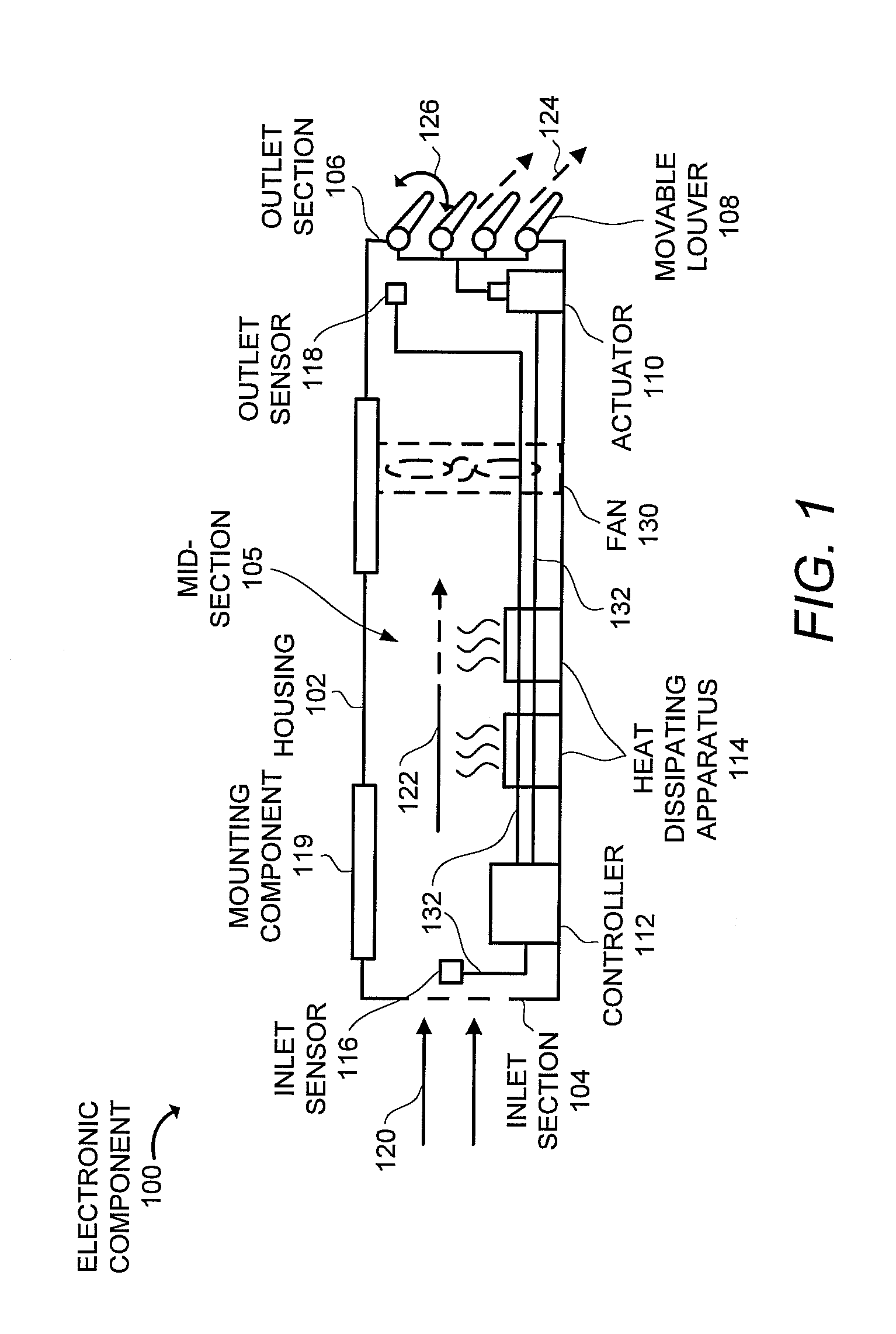
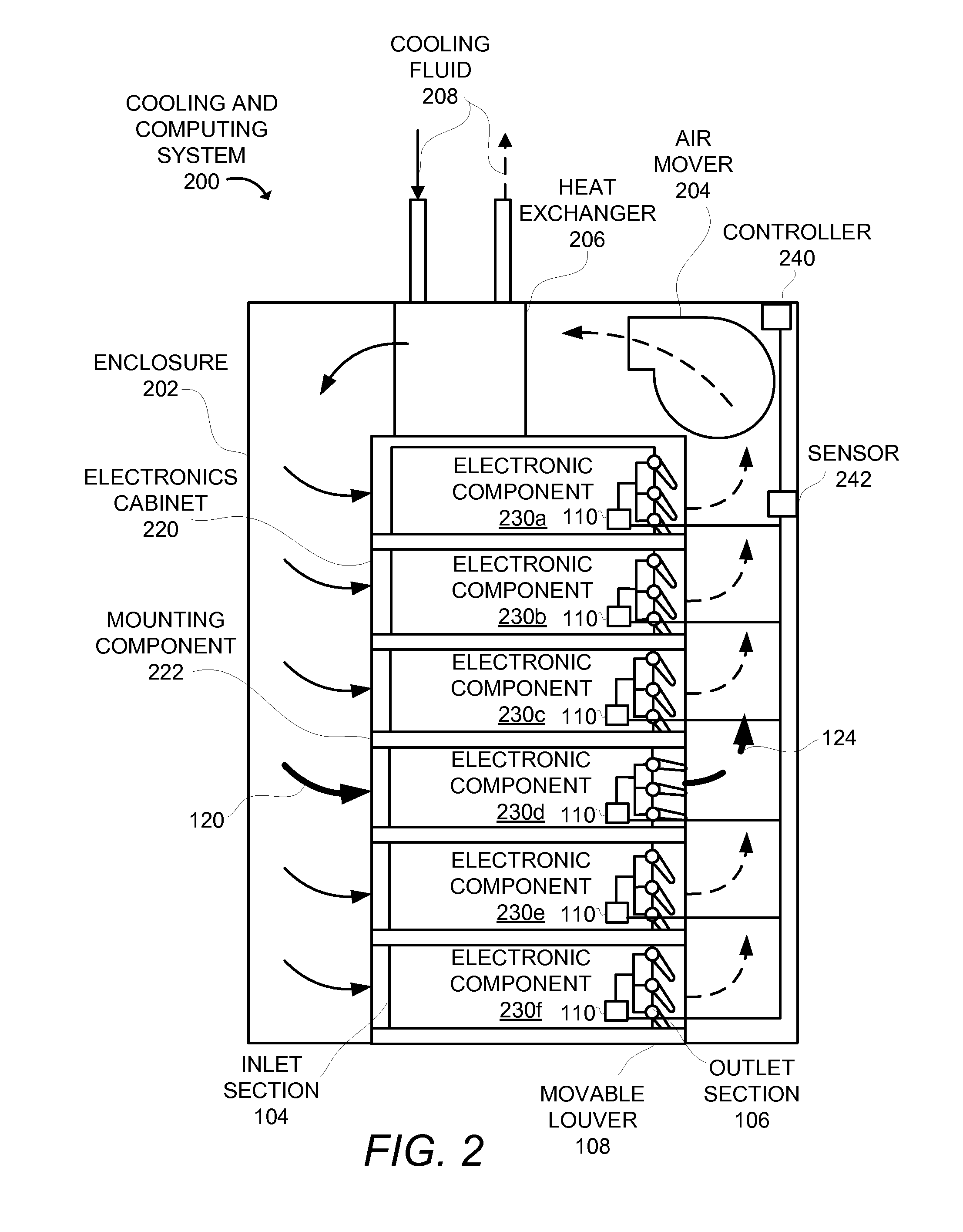
[0009]Disclosed herein is an electronic component that includes a housing having an inlet section, a mid-section, and an outlet section, mounting components for mounting the housing within an electronics cabinet, at least one movable louver positioned in at least one of the inlet section, the mid-section, and the outlet section, an actuator configured to manipulate the at least one movable louver to vary a volume flowrate of ai...
PUM
 Abstract
Description
Claims
Application Information