Actuation system for a wind turbine blade flap

a technology of actuator system and wind turbine blade, which is applied in the direction of boats, marine propulsion, chairs, etc., can solve the problems of cyclic pitch, wear on the actuator system, and the bearing of the pitch, and achieve the effect of easy deformation and easy handling of the flap

Active Publication Date: 2012-08-28
SIEMENS GAMESA RENEWABLE ENERGY AS
View PDF16 Cites 7 Cited by
  • Summary
  • Abstract
  • Description
  • Claims
  • Application Information

AI Technical Summary

Benefits of technology

[0006]It is therefore an objective of the present invention to provide an advantageous method of actuating a flap of a wind turbine blade, which overcomes the mentioned disadvantages. It is a further objective to provide a wind turbine rotor, which allows an advantageous flap regulation.
[0009]In the inventive method of actuating a flap in a wind turbine rotor blade a fluid is used for reversibly expanding an actuating element acting on a movable part of the flap by varying the fluid pressure in the actuating element. When no pressure is applied to the actuating element, the flap is, e.g. elastically, restored to its neutral position. When pressure is applied, the actuating element expands, deforms the flap and thereby deploys it in a desired direction. The deployed flap changes the aerodynamic properties of the blade profile and thereby the aerodynamic loads.
[0013]Generally, the actuating element can be a fluid hose, for instance a compressed air hose. The hose may be a standard product. In addition, the actuating element can have a flat cross-section in the deflated state, which would allow for easier fitting into the flap, or it can be folded which would increase the usable volume of the actuating element without significantly increasing the space required between the fixed part of the flap and the movable part of the flap. Furthermore, the actuating element can be integrated into the flap as an inner cavity which would allow it to form together with the flap so that no discrete add-on to the flap is necessary.
[0016]The flap may be composed continuously or as a series of flap elements which are located at different radial positions. The latter allows an easier handling and fitting of the flap. Further, the flap can have an external protrusion which is beneficial for easy deformation as desired under pressure.
[0017]The general advantage of the inventive method and the inventive wind turbine rotor lies in the replacement of known flap system actuators, typically complex arrangements based on electrical subsystems and electromechanical actuators and mechanisms. These known flap system actuators are now replaced by a very simple and cheap combination of a shape-changing actuation body and a suitably shaped flap structure. The described solution has the further advantage that it completely eliminates the need for electrical systems outboard of the blade root. All active systems can be located in the rotor hub and the actuation is performed by means that do not require service and are not vulnerable to, in particular, lightning strike.

Problems solved by technology

But for large wind turbines very heavy designs with enormous operational loads are the result of this practice.
A disadvantage of cyclic pitch is wearing on pitch actuator systems and pitch bearings.
Moreover, the regulation speed is limited, typically with response times in the order of seconds, because cyclic pitch requires the movement of large inertial masses in bearings with large frictional moments.
The main weaknesses of known flaps are the required complex actuators, typically electrical systems that may be highly vulnerable to especially lightning damage.

Method used


Image

  • Actuation system for a wind turbine blade flap
  • Actuation system for a wind turbine blade flap
  • Actuation system for a wind turbine blade flap

Examples


Embodiment Construction

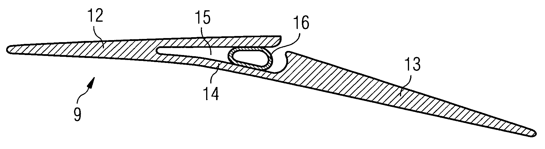
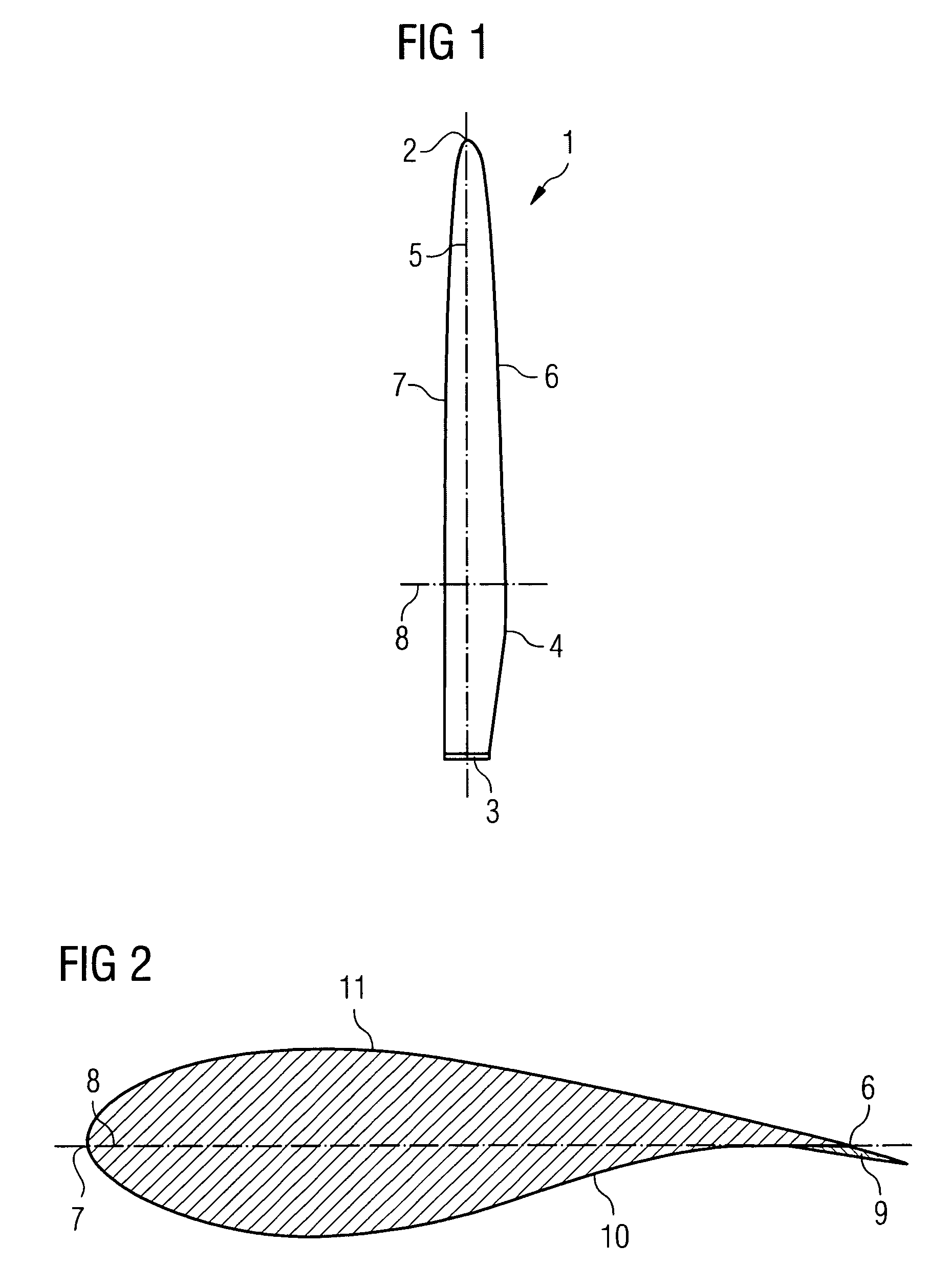
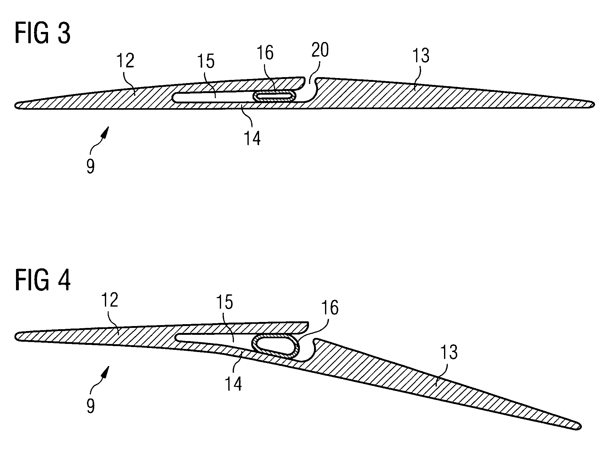
[0027]Now a first embodiment will be described with reference to FIGS. 1 to 4. FIG. 1 schematically shows a typical wind turbine rotor blade 1 in a top view. One can see in FIG. 1 the characteristic geometrical features of a turbine blade which are the blade root 3, the shoulder 4, the tip point 2, the leading edge 7, the trailing edge 6, the span line 5 and the chord line 8. At the blade root 3 the rotor blade is mounted to a rotor hub. The tip point 2 characterises the maximum radial position of the blade, measured from the blade root 3 along the span 5.

[0028]The span line 5 connects the blade root 3 with the tip point 2. The chord line 8 indicates the direction perpendicular to the span line 5. Chord means the maximum width of the turbine blade perpendicular to the span 5. Shoulder 4 means the radial position, measured from the blade root 3, where the chord has its maximum value. The trailing edge 6 is the downstream edge of the blade and extends from the blade root 3 along the s...


PUM


Abstract

Actuation system for a wind turbine blade flap.A method of actuating a flap (9) in a wind turbine rotor blade (1) is provided wherein a fluid is used for reversibly expanding an actuating element (16, 17, 19) acting a movable part (13) of the flap by varying the fluid pressure in the actuating element (16, 17, 19). Further, a wind turbine rotor with a rotor blade (1) comprising a flap (9) and a flap actuating system, where the flap comprises a fixed part (12) that is fixed to the rotor blade (1) and a movable part (13) that is movable relative to the fixed part (12), is disclosed, in which the flap actuating system comprises an actuating element (16, 17, 19) with a reversible changeable volume located between the movable part (13) of the flap and the fixed part (12) of the flap, a fluid within the actuating element (16, 17, 19) the pressure of which is settable and a pressure setting device which is designed to press fluid into or release fluid from the element (16, 17, 19) as to change its volume.

Description

CROSS REFERENCE TO RELATED APPLICATIONS[0001]This claims the benefits of European application No. 07010506.9 filed May 25, 2007 and is incorporated by reference herein in its entirety.FIELD OF INVENTION[0002]The present invention relates to a method of flap regulation of a wind turbine blade and a flap which allows such a regulation.BACKGROUND OF THE INVENTION[0003]In the context of wind turbine rotor blades it is generally intended to reduce the loads on the wind turbine blades. Until now the wind turbine blades and supporting structures are usually dimensioned so that they are able to withstand the dynamic loading that can occur under the conditions to which the turbine is certified. But for large wind turbines very heavy designs with enormous operational loads are the result of this practice. Consequently, various methods have been developed for an active reduction of operational loads.[0004]One method for an active reduction of operational loads is cyclic blade pitch as it is, e...

Claims


Application Information

Patent Timeline
Patent Type & Authority Patents(United States)
IPC IPC(8): B64C3/46
CPCF03D7/0232F05B2240/31Y02E10/721Y02E10/723Y02E10/72F05B2240/3052
Inventor STIESDAL, HENRIK
Owner SIEMENS GAMESA RENEWABLE ENERGY AS
Why Eureka
Try Eureka