Shoulder rehabilitation and exercise device

a shoulder and exercise technology, applied in the field of shoulder rehabilitation and exercise equipment, can solve the problems of pain, inflammation and loss of motion, and each of the muscles of the rotator cuff is susceptible to injury, and achieve the effects of increasing resistance, simple increasing force, and increasing rotation speed

Active Publication Date: 2012-08-28
BINNS MATTHEW +2
View PDF16 Cites 12 Cited by
  • Summary
  • Abstract
  • Description
  • Claims
  • Application Information

AI Technical Summary

Benefits of technology

[0035]In certain preferred embodiments of the present invention, the damper includes a manually adjustable hydraulic fluid flow valve which can be operated by a user in order to select a higher or lower range of damper resistance. That is to say, the damper utilized in all embodiments of the present invention provides—automatically—an increase in resistance to arcuate motion of the restrictor arm in response to increased application of force—and thus an increase in acceleration—applied to the hand grip of the actuator arm by a user. Conversely, the damper utilized in all embodiments of the present invention provides a decrease in resistance in response to a decreased application of force—and thus a decrease in restrictor arm acceleration—applied to the hand grip by a user. The resistance of such dampers, from the lowest to highest responsive resistance defines a range of resistance. Certain preferred embodiments of the present invention utilize a damper having an adjustable hydraulic valve which is operable by a user (as described below) enables an increase or decrease in the range of automatic resistance provided by the damper.
[0066]The rehabilitation and exercise device of the present invention protects a user from deleterious effects of rehabilitation and / or exercise device inertia and stored (potential) energy. More specifically, when a user stops applying force to the actuating arm of the device, the arcuate movement of the arm terminates—without the device resisting termination of movement via application of inertial, kinetic or stored energy that would otherwise have the effect of opposing such termination of movement—. Simply put, upon termination of the application of force by a user, the device of the present invention ceases the above-described arc-like movement so as to protect a user from the action of inertial or the release of stored potential energy that might otherwise cause injury.

Problems solved by technology

However, due largely to its high flexibility, the shoulder is frequently subject to injury leading to pain, inflammation and loss of motion.
Each of the muscles of the rotator cuff are susceptible to injury such as sprains and muscle tears which can be debilitating.
The supraspinatus muscle and tendon is especially susceptible to such injury and is the most commonly injured part of the rotator cuff due, in large part, to its position and path of contraction.
However, any of these muscles and associated tendons can an are involved in rotator cuff injuries.
Utilizing free weight exercise was of limited value in that, depending upon the user's position, it is difficult to obtain consistent resistance through, for example, a complete 180 degrees of internal or external rotation.
A handheld weight, following an arch-like movement, will not provide consistent resistance.
Such techniques also make no allowance for control and achievement of a safe range of motion.
Holding a free weight by hand, especially in regard to a rehabilitation exercise, may be dangerous in that the potential energy associated with the weight might cause a user to over-extend his or her movements —go beyond a range of motion in which such movement is safe—.
Also, if a user should suffer a spasm, sudden pain or lose consciousness, the potential energy stored in the free weight or the momentum developed could cause further injury to the user or others.
In addition, performing both internal and external rotation of the shoulder with weights would most likely require a user to continually change position.
However, utilizing such an exercise device subjects a user to varying amounts of resistance as the band or tube is stretched and, similar to the use of weights, subjects the user to the danger of stored potential energy within the elastic posing a danger of injuring the user.
However, as the case with hand weights and elastics, pulley machines also store potential energy during use which can result in the aforementioned injuries.
The disclosed device utilizes a stack of weights to provide resistance to a user's motion which, of course, does entail the storing of potential energy and generation of momentum that can cause the aforementioned problems.
This device, as discussed above in regard to free weight exercise and elastic resistance machines, stores potential energy and develops considerable momentum which may be damaging to a user and includes no means of controlling the range of motion during inward or outward rotation.
However, the device disclosed in this patent provides no means to provide limitation to internal or external rotation of a shoulder.
However, the means utilized to adjust the angular relation of a user's upper and lower arm disclosed in U.S. patent application Ser. No. 12 / 156,199 necessarily changes the amount of force required to operate the device (at a given rate of speed) due to the effect of such adjustment lengthening or shortening the moment arm—or the effective length of the lever—of the below described actuator arm.
Therefore, the '191 device is unable, without the use of additional adjustments, to provide a uniform resistance for a user as the elevation of the actuator is adjusted to accommodate a particular user's arm dimensions or the height of a table and / or chair utilized when operating dame.

Method used


Image

  • Shoulder rehabilitation and exercise device
  • Shoulder rehabilitation and exercise device
  • Shoulder rehabilitation and exercise device

Examples


Embodiment Construction

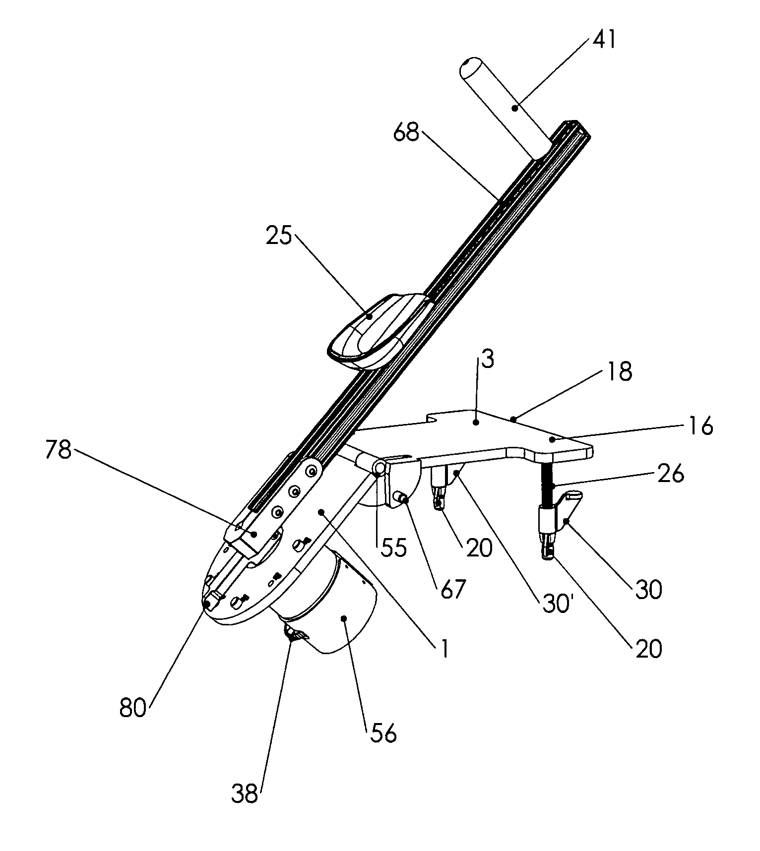
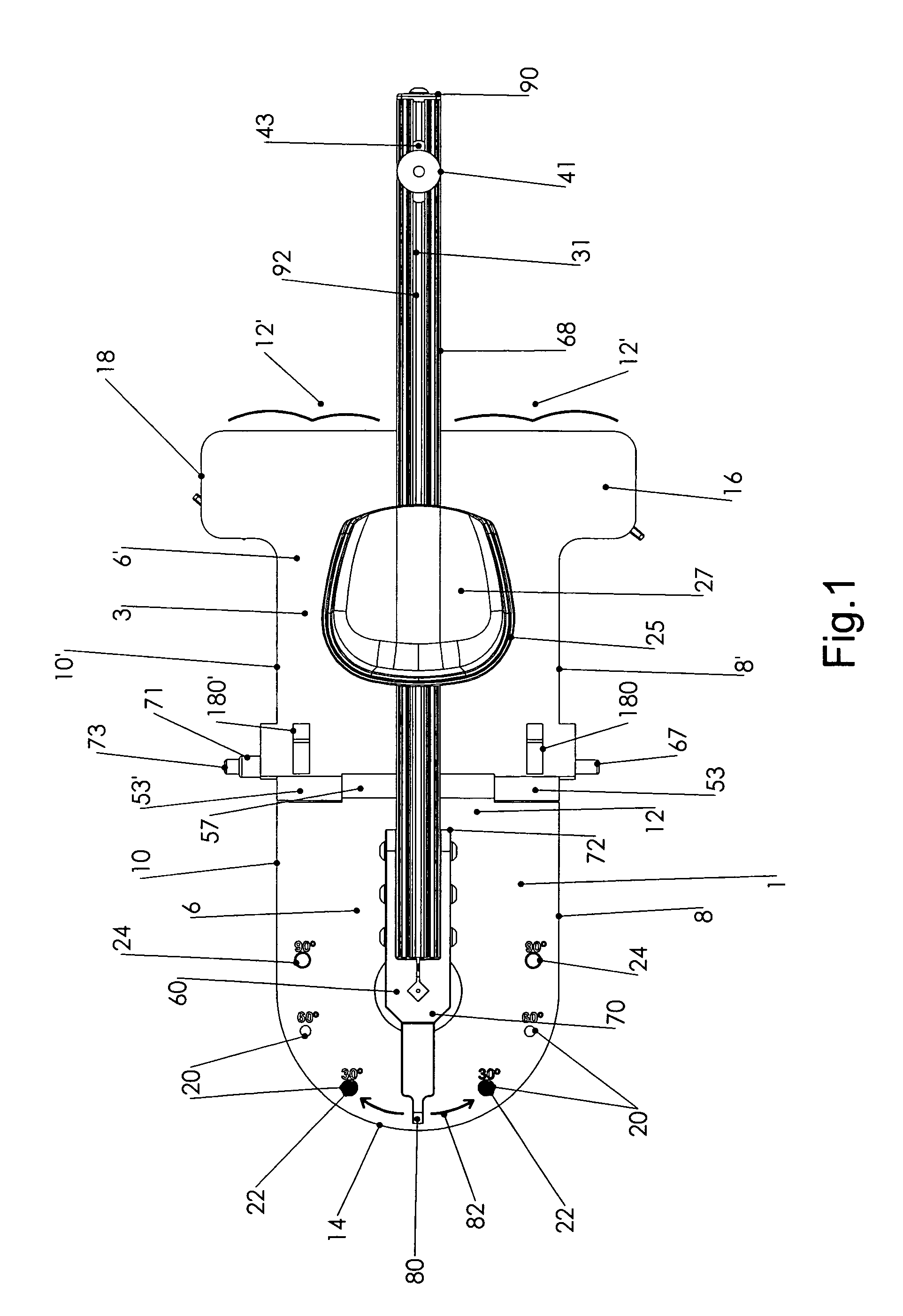
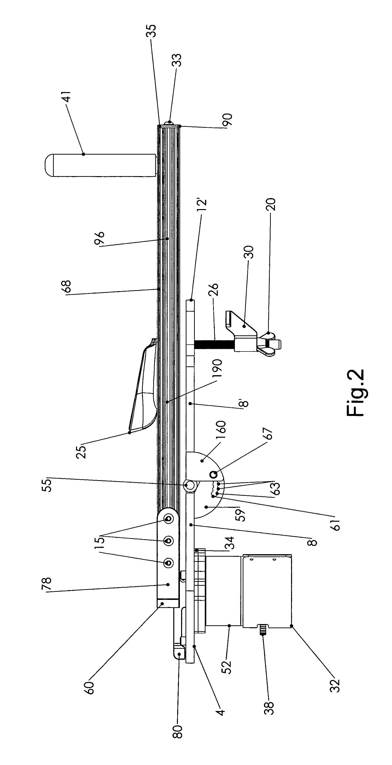
[0081]The drawing FIGS. (1-13) illustrate a preferred embodiment of the shoulder therapeutic and exercise device of the present invention which incorporates an articulating two section base plate. As illustrated in the figures, the base plate is configured as separate proximal 1 and distal 3 sections. The proximal base plate section has a lower planar surface 4, an upper planar surface 6, a right edge 8 a left edge 10 a distal portion 12 and a proximal portion 14. Likewise, the distal base plate section has a lower surface 4′, an upper surface 6′, a right edge 8′ a left edge 10′ a distal portion 12′ and a proximal portion 14′. The two section base plate may also be described as having a longitudinal axis running from the proximal to distal portions of each section of the base plate, along the midline thereof, the longitudinal axis of each base plate aligned with one another when the planar upper and planar lower surfaces of the base plates are also aligned, one with the other along ...


PUM


Abstract

A shoulder rehabilitation and exercise device is disclosed which enables a user to perform internal and external rotations of both right and left shoulder. The device is comprised of a base plate, hydraulic damper, restrictor arm, actuator arm, elbow cup and hand grip. A smooth, fluid-like movement is achieved during performance of arcuate internal and external shoulder rotations while also providing automatic increases and decreases in resistance to such motion in response to user effort. In certain preferred embodiments, in addition to such automatic adjustment of resistance, the device includes a means of manually adjusting resistance. The device may be utilized to perform the aforementioned internal and external rotations on a user's right or left side without need for making any adjustments to the machine. Range of motion limitations may be set to control the arcuate degree of internal and external rotations performed. Adjustment in the elevation of a user's forearm via adjustment of a two section, pivoting base plate is provided that enables elevation adjustment without effecting operating resistance. The actuator arm includes an adjustable elbow cup and adjustable hand grip. The device does not store potential energy or produce sufficient momentum to oppose a user's immediate and safe termination of motion.

Description

RELATED APPLICATIONS[0001]This application is a continuation-in-part application based upon U.S. patent application Ser. No. 12 / 156,199 filed May 30, 2008 now U.S. Pat No. 7,976,444 which, in turned, claimed the benefit of U.S. Provisional Application No. 60941168 filed on May 31, 2007, the contents of which prior applications are hereby incorporated by reference.TECHNICAL FIELD[0002]The present invention relates to the field of rehabilitation and exercise equipment. More specifically, a rehabilitation and exercise device is disclosed herein specifically adapted and configured to enable a user to strengthen and increase the range of motion of muscles associated with internal and external rotation of the shoulder.BACKGROUND OF THE ART[0003]The shoulder joint is the most mobile and flexible joint in the human body. This joint controls the position of the upper arm and, due to the high flexibility of the joint, enables a tremendous range of motion. However, due largely to its high flex...

Claims


Application Information

Patent Timeline
Patent Type & Authority Patents(United States)
IPC IPC(8): A63B21/008
CPCA61H1/0281
Inventor BINNS, MATTHEWPROTAS, EUGENE DAVIDAVENARIUS, SCOTT
Owner BINNS MATTHEW
Why Eureka
Try Eureka