Thin slot antenna having cavity, antenna power feeding method, and RFID tag device using the antenna and the method

a technology of rfid tag and cavity, which is applied in the direction of resonant antennas, flexible aerials, collapsible antennas, etc., can solve the problems of deformation of one of the conditions, and achieve the effects of improving the efficiency of the antenna, reducing weight, and high flexibility

Active Publication Date: 2012-08-28
HITOSHI KITAYOSHI
View PDF27 Cites 15 Cited by
  • Summary
  • Abstract
  • Description
  • Claims
  • Application Information

AI Technical Summary

Benefits of technology

[0030]The thin slot antenna having a cavity described in claim 4 is characterized in that the dielectric sheet is formed of any one material of polypropylene and polystyrene. Particularly, polypropylene is preferable in view of the advantage of the present invention.
[0031]For the dielectric constant (1 kHz), polypropylene is in the range of 2.0 to 2.5, and polystyrene is in the range of 2.4 to 2.6. The other resins such as polyethylene may be properly used.
[0032]In this occasion, because a highly expanded material is used as the dielectric sheet to bring the dielectric constant close to that of air, dielectric losses are reduced to improve the efficiency of the antenna as well as high flexibility and a reduction in weight can be achieved.
[0033]The thin slot antenna having a cavity described in claim 5 is characterized in that the thickness of the dielectric sheet ranges from 0.01 to 0.05λ.
[0034]On this occasion, preferably, the size of the dielectric sheet is in the range of 2 mm to 3 mm, in consideration of processing properties and the range of changes in the thickness caused by external force. In addition, when the antenna is used in a 2.45 GHz band RFID, the thickness of 2 mm is 0.016λ, and when used in a 950 MHz band RFID, the thickness of 3 mm is 0.0095λ.
[0035]The thin slot antenna having a cavity described in claim 6 is characterized in that the conductive foil or the conductive thin film is formed of a single layer or a composite layer containing any one material of aluminum and copper.

Problems solved by technology

However, because it is not considered in typical antennas that antennas are freely deformed for use, a rigid material of relatively high shape retention is used for them.
On the other hand, as the antenna for use in the above-described wearable computer, one of its conditions is deformable.

Method used


Image

  • Thin slot antenna having cavity, antenna power feeding method, and RFID tag device using the antenna and the method
  • Thin slot antenna having cavity, antenna power feeding method, and RFID tag device using the antenna and the method
  • Thin slot antenna having cavity, antenna power feeding method, and RFID tag device using the antenna and the method

Examples


Embodiment Construction

[0077]Next, embodiments of a thin slot antenna having a cavity and an RFID tag device according to the present invention will be described with reference to the drawings.

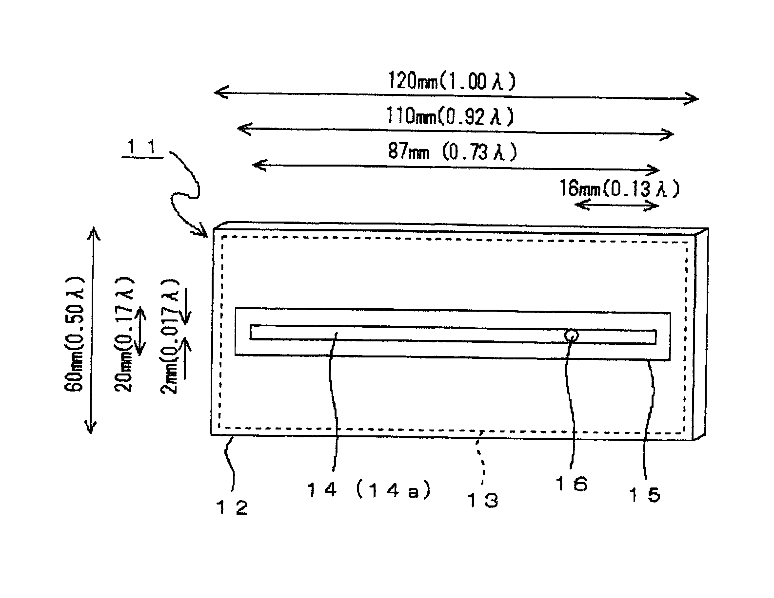
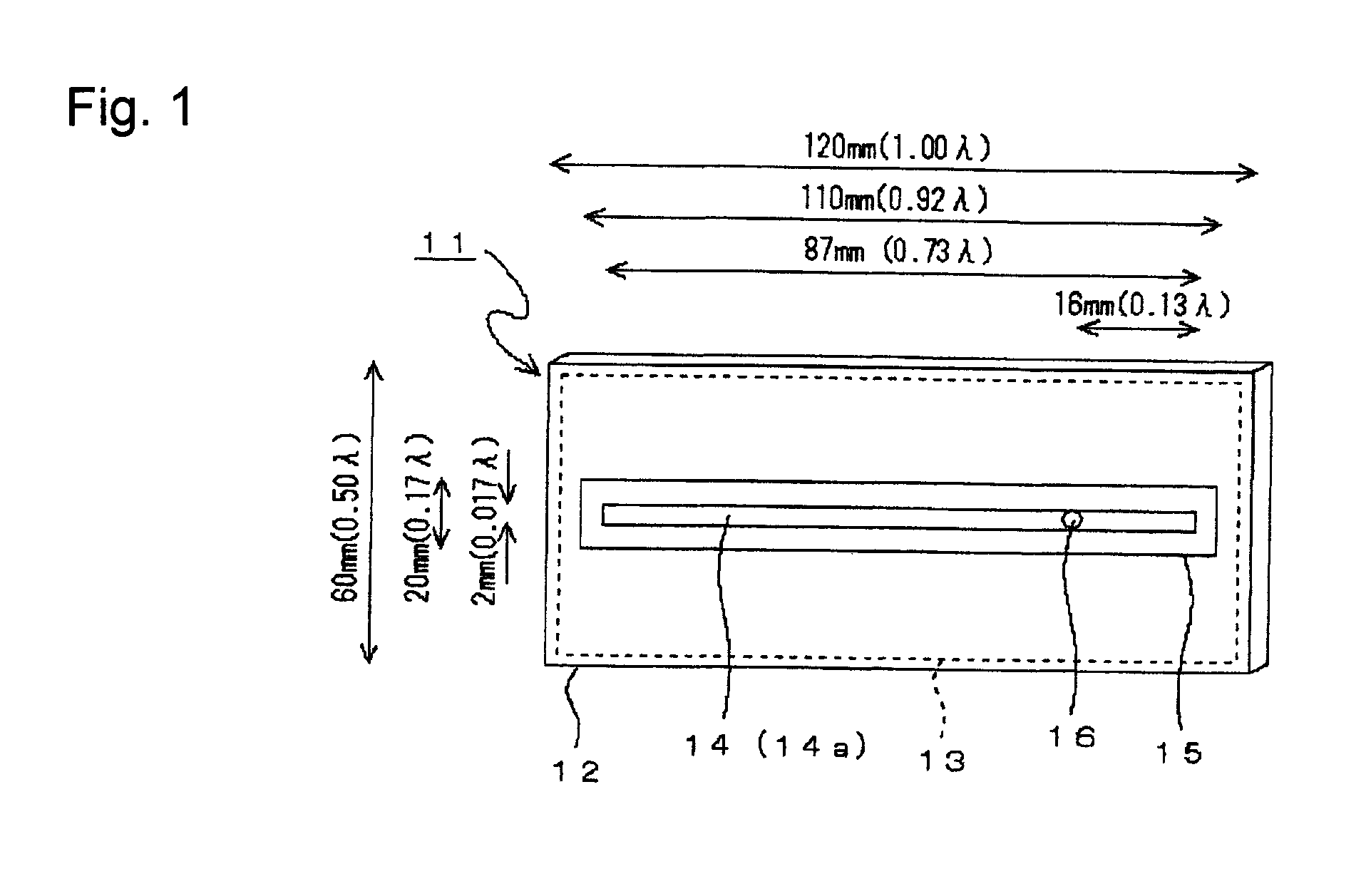
[0078]FIG. 1 is a perspective view depicting a thin slot antenna having a cavity, showing an embodiment of the present invention.

[0079]In FIG. 1, a bag-shaped product 11 having a cavity 12 is configured of conductive foil, a soft dielectric sheet 13 is provided inside the cavity 12, and a slot 14 is provided on one side of the conductive foil by partially removing the conductive foil. This bag-shaped product becomes a thin slot antenna having a cavity for use in wireless communications with flexibility such that the antenna can be mounted on the flat surface or the curved surface.

[0080]Hereinafter, the embodiment will be described more in detail.

[0081]In FIG. 1, the thin slot antenna having a cavity (simply referred to as the “antenna” below) 11, for example, has the cavity 12 (resonance cavity) in a bag shape, whic...


PUM


Abstract

A highly efficient thin slot antenna having a cavity and an RFID tag device are provided, in which such flexible properties can be provided to the antenna that the antenna can be worn on the curved surface of a human body, an object, or the like as well as the antenna can be relatively freely deformed, and changes in the characteristics caused by deformation and changes in the characteristics caused by a product to mount the antenna thereon. are extremely small. Conductive foil such as aluminum or foil vapor deposited with conductive metal such as aluminum is used to form a bag shape for configuring a bag-shaped product having a cavity (12). A relatively soft dielectric sheet (13) is provided inside the cavity (12), and a slot (14) is provided lengthwise on one side of the bag-shaped product at the center position in the width direction.

Description

TECHNICAL FIELD[0001]The present invention relates to a thin slot antenna having a cavity, an antenna feeding method, and an RFID tag device using the antenna and the method.BACKGROUND ART[0002]Non-Patent Document 1: Masato Tanaka, RFID by using fabric antenna, Proceedings of IEICE General Conference 2006, B-1-173, March 2006[0003]Non-Patent Document 2: Wearable microstrip antenna for satellite communications, IECE Transaction on Communications, vol. E87-B, no. 8, August 2004[0004]Patent Document 1: JP 2002-352199 A[0005]Patent Document 2: JP 2005-236858 A[0006]In recent years, attention is focused on ubiquitous computing as the information environment in which computers exist everywhere in life and society and computers autonomously work together and operate to strongly support the everyday life of people, and this is partially realized.[0007]In the ubiquitous computing, a computer can perform processing as automatically working together with other computers while referring to pers...

Claims


Application Information

Patent Timeline
Patent Type & Authority Patents(United States)
IPC IPC(8): H01Q13/00H01Q13/10
CPCH01Q1/085H01Q13/18
Inventor KITAYOSHI, HITOSHISAWAYA, KUNIO
Owner HITOSHI KITAYOSHI
Why Eureka
Try Eureka