
Leaky-wave antenna capable of multi-plane scanning

a technology of antennas and antennas, applied in the direction of individual energised antenna arrays, resonant antennas, radiating element structural forms, etc., can solve the problems of plurality of shortages, inconvenient operation, and the ability of antennas to improve system performan

Inactive Publication Date: 2012-08-28
NAT CHIAO TUNG UNIV
View PDF8 Cites 1 Cited by
  • Summary
  • Abstract
  • Description
  • Claims
  • Application Information

AI Technical Summary

Benefits of technology

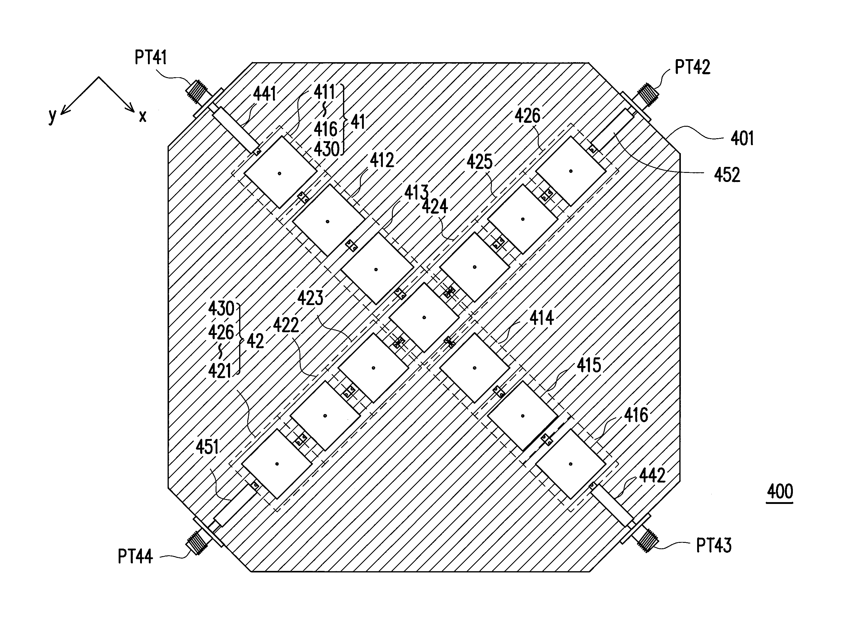
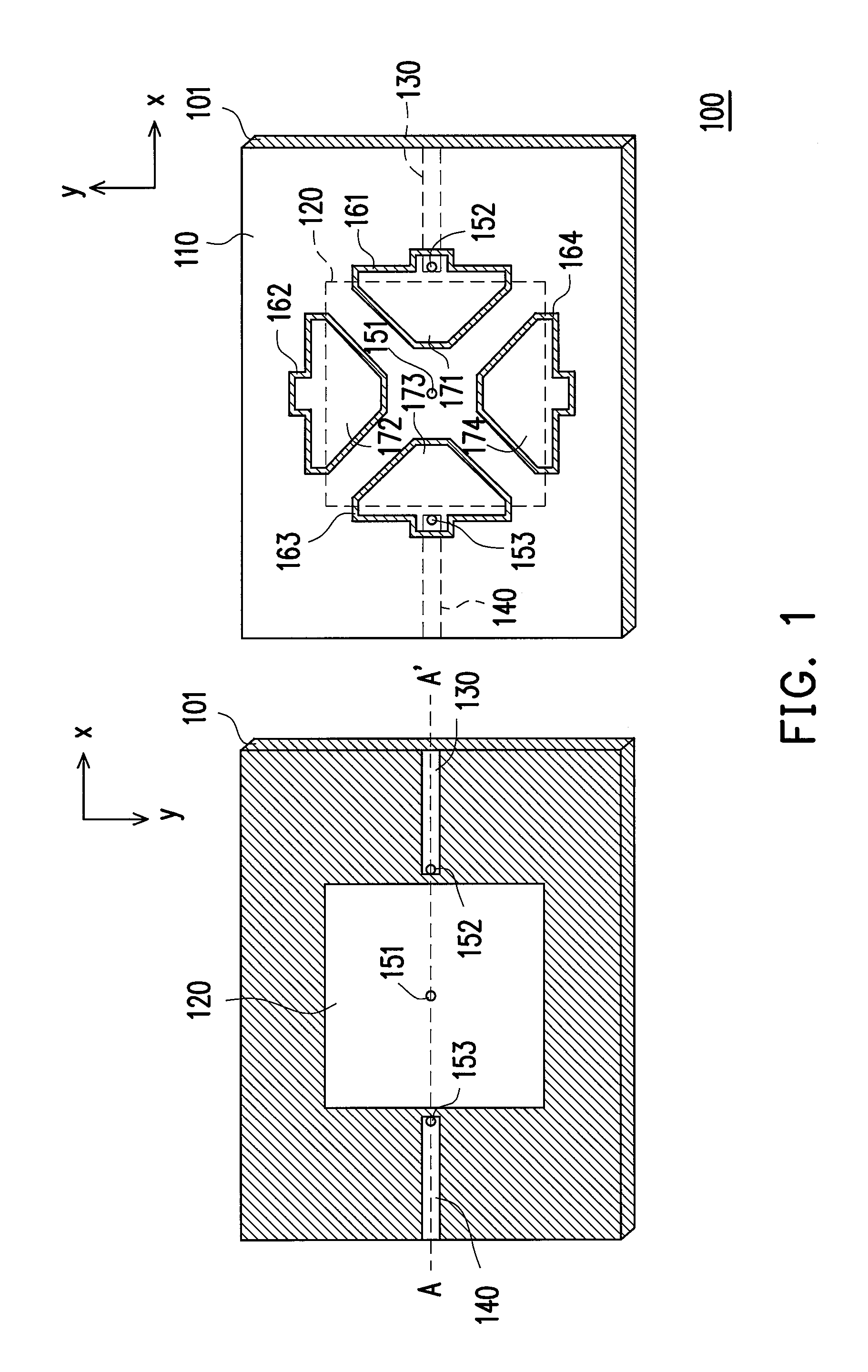
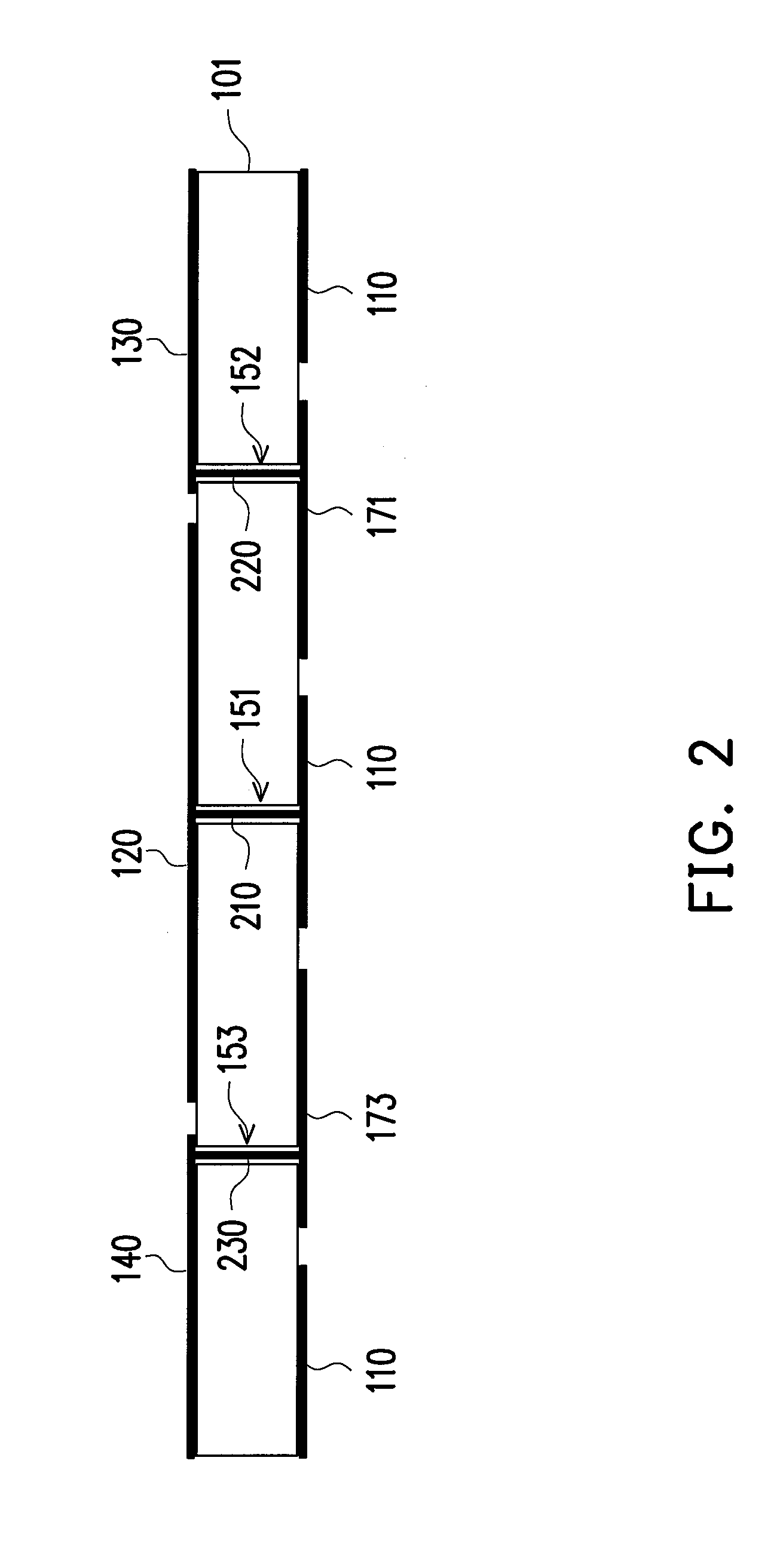
[0009]The present invention is directed to a leaky-wave antenna capable of multi-plane scanning, which has a beam scanning function and a beam switching function, and also has an advantage of miniaturization due to usage of a planar structural design.
[0014]According to the above descriptions, in the present invention, the antenna series having the beam scanning function are disposed in intersection, and the control units are used to control conduction states of the transmission paths. In this way, the leaky beam radiated by the leaky-wave antenna capable of multi-plane scanning is switched to one of the scanning planes, and an original sweep-frequency characteristic of the antenna series is maintained. Moreover, the leaky-wave antenna capable of multi-plane scanning has a planar structural design, so that it can be miniaturized. Since the antenna series are disposed in intersection, the circuit features of the leaky paths of the antenna are similar, so that usage of complicated matching circuits is unnecessary.

Problems solved by technology

Moreover, since an antenna is one of indispensable elements in a wireless communication system, to design an antenna capable of improving a system performance is an important issue.
Although the current techniques can achieve the beam switching effect, there is a plurality of shortages.
For example, regarding the technique of changing different ports of the coupler to serve as the input port, the unused ports have to be connected with matched impedances for normal operation, which may lead to an operation inconvenience.
Regarding the Yagi antenna designed according to a monopole antenna technique, etc., the antenna does not have a low profile characteristic, and slimness of the antenna cannot be implemented.
Moreover, regarding the beam-forming technique, a complicated and large-area feed-in network and an antenna array have to be used to implement switching of the multiple beam directions, so that miniaturization thereof is hard to be achieved.
Moreover, none of the above methods can achieve a beam scanning function.

Method used


Image

  • Leaky-wave antenna capable of multi-plane scanning
  • Leaky-wave antenna capable of multi-plane scanning
  • Leaky-wave antenna capable of multi-plane scanning

Examples


Embodiment Construction

[0026]Reference will now be made in detail to the present preferred embodiments of the invention, examples of which are illustrated in the accompanying drawings. Wherever possible, the same reference numbers are used in the drawings and the description to refer to the same or like parts.

[0027]In the present invention, antenna series are disposed in intersection to form a leaky-wave antenna capable of multi-plane scanning, and each of the antenna series is formed by serially connecting a plurality of antenna units. Moreover, control units are disposed aside the intersection of the antenna series, so that a leaky beam radiated by the leaky-wave antenna capable of multi-plane scanning can be switched to one of scanning planes. Moreover, each of the antenna units is designed to be a composite right / left-hand (CRLH) transmission line structure, so that the leaky beam can implement a sweep-frequency mechanism through the antenna units. To further convey the spirit of the present invention...


PUM


Abstract

A leaky-wave antenna capable of multi-plane scanning is provided. The leaky-wave antenna includes a substrate, a first antenna series, a second antenna series and a plurality of control units. The first antenna series intersects with the second antenna series to share a predetermined antenna unit among many antenna units. A part of the antenna units is connected in series to extend from a first and a second transmission lines of the predetermined antenna unit to compose the first antenna series, and the other antenna units are connected in series to extend from a third and a fourth transmission lines of the predetermined antenna unit to compose the second antenna series. The control units control the transmission paths between the first to the fourth transmission lines and the antenna units, and switch a leaky beam to different scanning planes, wherein the leaky beam scans with frequency variation through the antenna units.

Description

CROSS-REFERENCE TO RELATED APPLICATION[0001]This application claims the priority benefit of Taiwan application serial no. 98144536, filed on Dec. 23, 2009. The entirety of the above-mentioned patent application is hereby incorporated by reference herein and made a part of specification.BACKGROUND OF THE INVENTION[0002]1. Field of the Invention[0003]The present invention relates to an antenna. More particularly, the present invention relates to a leaky-wave antenna capable of multi-plane scanning.[0004]2. Description of Related Art[0005]With booming development of wireless communication technology and liberalization of telecommunication, various communication protocol specifications and techniques are provided for achieving a better communication quality in an effective bandwidth. Moreover, since an antenna is one of indispensable elements in a wireless communication system, to design an antenna capable of improving a system performance is an important issue.[0006]In a current commun...

Claims


Application Information

Patent Timeline
Patent Type & Authority Patents(United States)
IPC IPC(8): H01Q13/20
CPCH01Q13/20H01Q13/206H01Q21/061H01Q21/065H01Q21/08
Inventor CHANG, RONG-YUANCHEN, FU-CHIARNG
Owner NAT CHIAO TUNG UNIV
Learn More