Liquid crystal display

a liquid crystal display and display technology, applied in the field of display, can solve the problem of inconvenient repair of the conventional backlight module, and achieve the effect of improving the repair efficiency of the light source unit and improving the light incident efficiency of the light guide pla

Active Publication Date: 2012-08-28
AU OPTRONICS CORP
View PDF6 Cites 3 Cited by
  • Summary
  • Abstract
  • Description
  • Claims
  • Application Information

AI Technical Summary

Benefits of technology

[0010]The present invention relates to a liquid crystal display whose light source unit is easily to be replaced.
[0011]The present invention further relates to a liquid crystal display for improving light emitting efficiency of a light source unit of the liquid crystal display.
[0025]In the liquid crystal display of the present invention, due to the light source unit being detachable, when the light source unit is failed, only the light source unit needs to be detached for replacing a new one. Therefore, the liquid crystal display of the present invention can improve repair efficiency of the light source unit. Furthermore, in the liquid crystal display of the present invention, the light source unit can be fixed at a suitable position, so light incident efficiency of the light guide plate can be improved.

Problems solved by technology

Therefore, it is inconvenient to repair the conventional backlight module 100.

Method used


Image

  • Liquid crystal display
  • Liquid crystal display
  • Liquid crystal display

Examples


Embodiment Construction

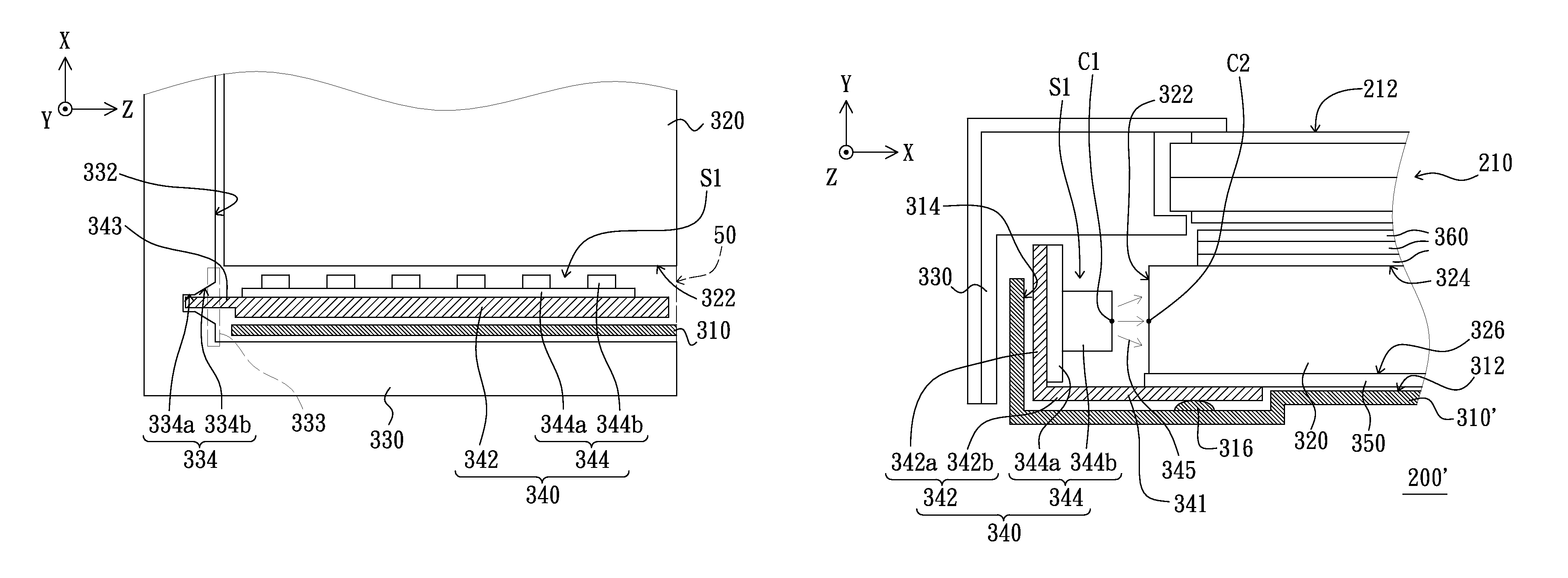
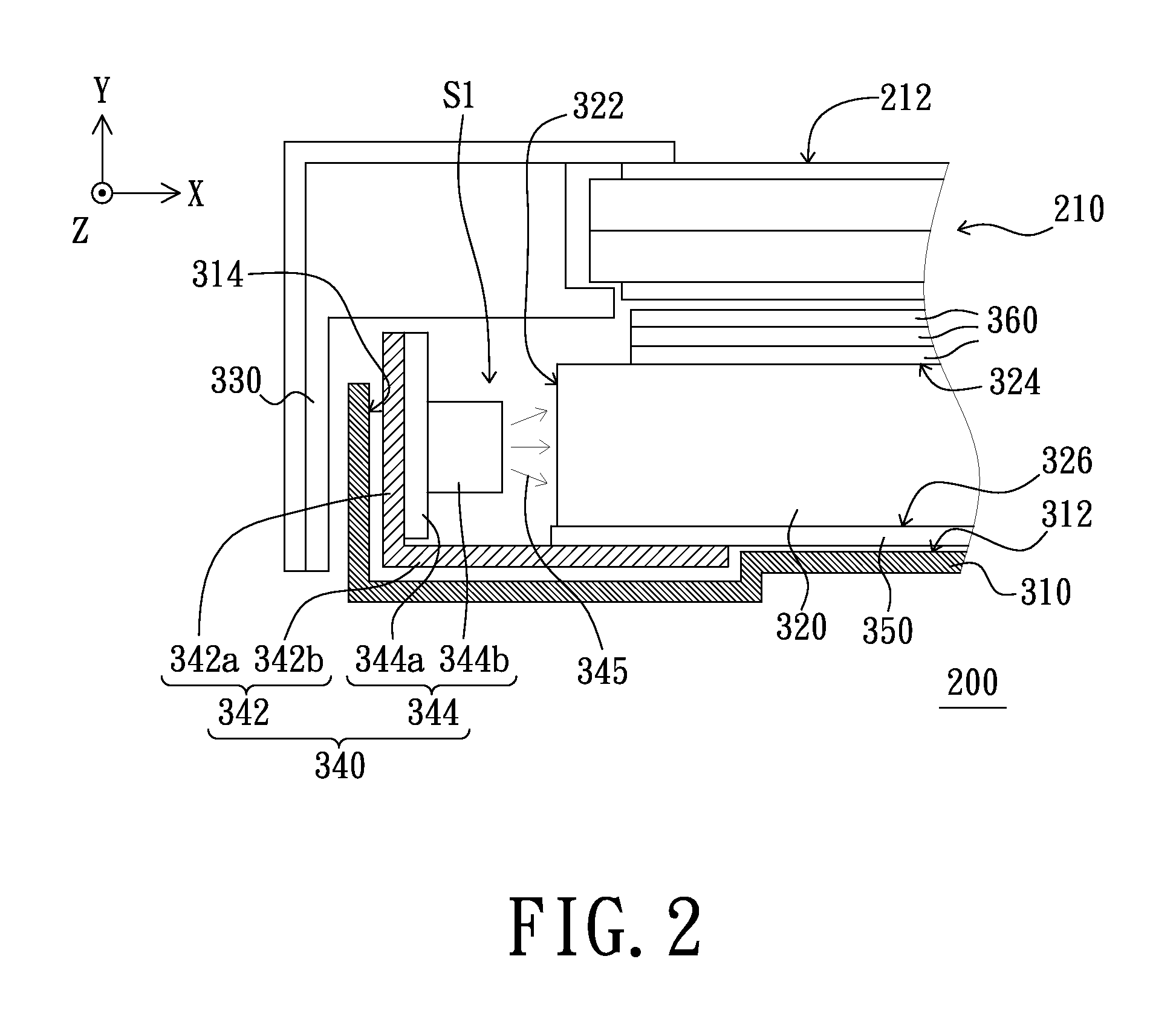
[0035]FIG. 2 is a schematic view of a liquid crystal display according to an embodiment of the present invention, FIG. 3A is a schematic top view of a light guide plate, a frame, a first side wall of a back bezel and a light source unit of FIG. 2, and FIG. 3B is a schematic three-dimensional view showing the light source unit of FIG. 2 being mounted into an accommodation space along a predetermined direction. Referring to FIGS. 2, 3A and 3B, the liquid crystal display 200 of the present embodiment includes a liquid crystal display panel 210, a back bezel 310, a light guide plate 320, a frame 330 and a light source unit 340. The light guide plate 320 is disposed on a bottom 312 of the back bezel 310. The light guide plate 320 has a light incident surface 322 opposite to a first side wall 314 of the back bezel 310 and spaced at a distance from a first side wall 314 of the back bezel 310. There is an accommodation space S1 between the first side wall 314 of the back bezel 310 and the l...


PUM

PropertyMeasurementUnit
distanceaaaaaaaaaa
weightaaaaaaaaaa
sizeaaaaaaaaaa

Abstract

A liquid crystal display (LCD) includes a back bezel, a light guide plate (LGP) having a light incident surface opposite to a first side wall of the back bezel, an LCD panel disposed above the LGP, a frame and a light source unit. There is an accommodation space between the first side wall of the back bezel and the light incident surface of the LGP. The frame is assembled with the back bezel to fix and surround the LGP and the LCD panel. A portion of the frame extends across the upper side of the accommodation space. A portion of the second side wall of the frame is opposite to the entrance side of the accommodation space and has a first securing portion. The light source unit has a second securing portion. When the light source unit is mounted / attached into the accommodation space, the second securing portion is jointed the first securing portion to secure the light source unit.

Description

CROSS-REFERENCE TO RELATED APPLICATIONS[0001]This application is based upon and claims the benefit of priority from the prior Taiwanese Patent Application No. 097138469, filed Oct. 6, 2008, the entire contents of which are incorporated herein by reference.BACKGROUND[0002]1. Field of the Invention[0003]The present invention relates to a display, and more particularly to a liquid crystal display.[0004]2. Description of the Related Art[0005]With the development of flat panel display technique, flat panel displays (FPDs) that have advantages of light in weight, small in size and low power consumption are becoming more and more popular. Typically, the flat panel displays include liquid crystal displays (LCDs), plasma panel displays (PDPs), organic light emitting diode displays (OLED displays) and electrophoretic displays (EPDs). Among the flat panel displays, the liquid crystal displays are most widely used.[0006]The liquid crystal display includes a liquid crystal display panel and a ba...

Claims


Application Information

Patent Timeline
Patent Type & Authority Patents(United States)
IPC IPC(8): G02F1/13357
CPCG02F1/133608G02F1/133615
Inventor YEN, TUNG-ICHEN, CHUNG-JUNG
Owner AU OPTRONICS CORP
Why Eureka
Try Eureka