
Apparatus for constructing ring network

a technology of ring network and apparatus, applied in the field of apparatus for constructing ring network, can solve the problems of unflexible network structure of network structure, below-mentioned problems to be solved,

Active Publication Date: 2012-08-28
ALAXALA NETWORKS
View PDF9 Cites 9 Cited by
  • Summary
  • Abstract
  • Description
  • Claims
  • Application Information

AI Technical Summary

Benefits of technology

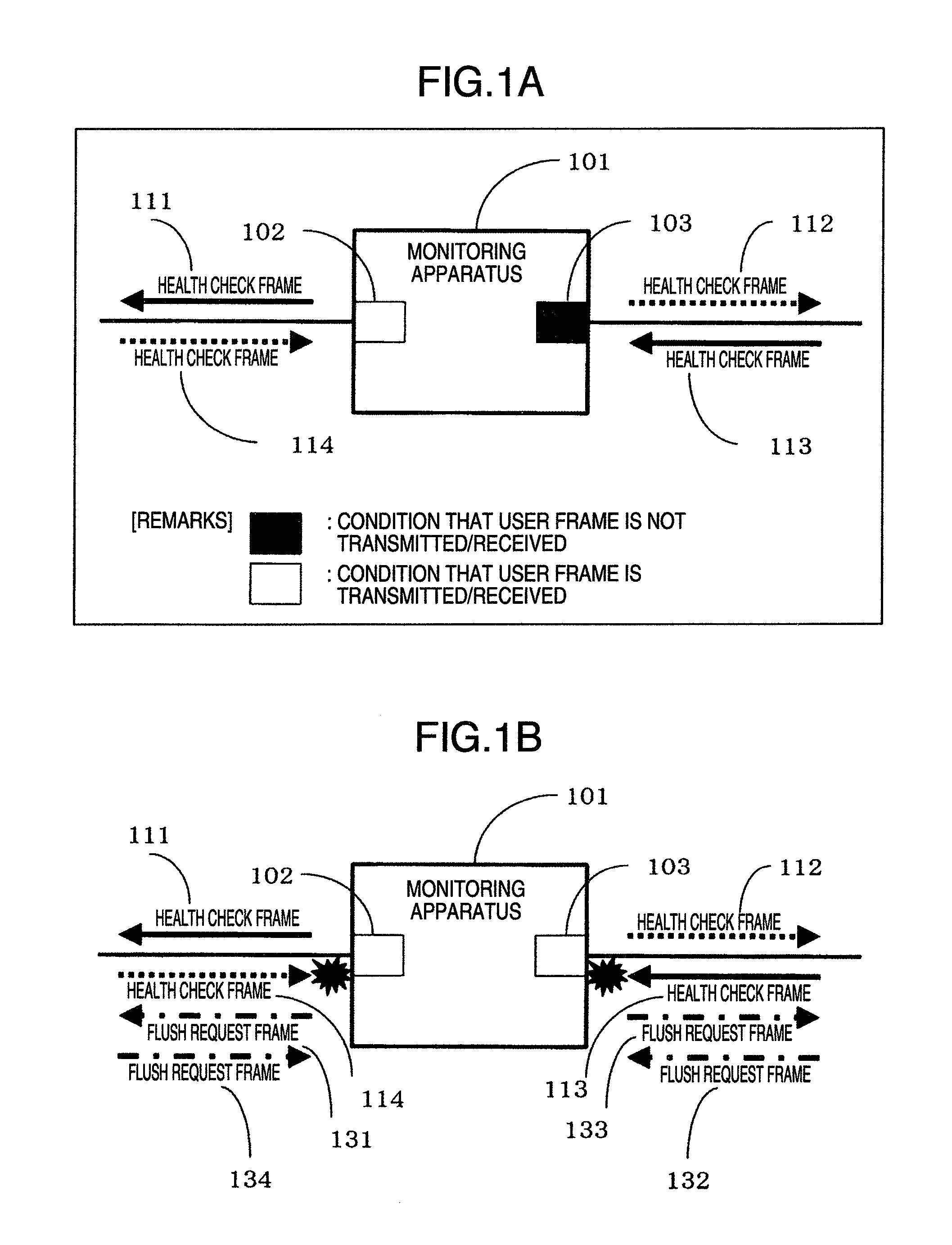
[0009]An object of the present invention has been made to solve the above-described problems, and therefore, is to provide an apparatus capable of realizing high-speed switching of communication routes, capable of preventing an occurrence of a loop which is caused by an one-directional failure of a link within a ring network, and capable of realizing a simple and flexible structure constructed by coupling a plurality of ring networks, and further, capable of avoiding a construction of a loop caused by a failure of a specific link.
[0011]In accordance with the present invention, the monitoring apparatus which constructs the ring network judges whether or not relaying of a user frame is permitted by checking whether or not the periodically transmitted health check frame is received. As a consequence, the high-speed switching of the routes can be realized.

Problems solved by technology

However, this redundant protocol has the below-mentioned problems to be solved.
Furthermore, in another network structure that a plurality of ring networks are coupled to each other and coupled apparatuses become redundant, there is such a limitation that an apparatus at the coupling portion must be a monitoring apparatus.
As a consequence, there is another problem to be solved that the network structure cannot have a flexible network structure.
Also, as a problem specific to a ring network, in the case that the plurality of ring networks are coupled to each other and apparatuses of coupling portions are made redundant, if a failure happens to occur in a link between the apparatuses made redundant, then the following problem occurs.

Method used


Image

  • Apparatus for constructing ring network
  • Apparatus for constructing ring network
  • Apparatus for constructing ring network

Examples


Embodiment Construction

[0026]Referring now to drawings, a detailed description is made of a ring network constructing apparatus according to an embodiment of the present invention.

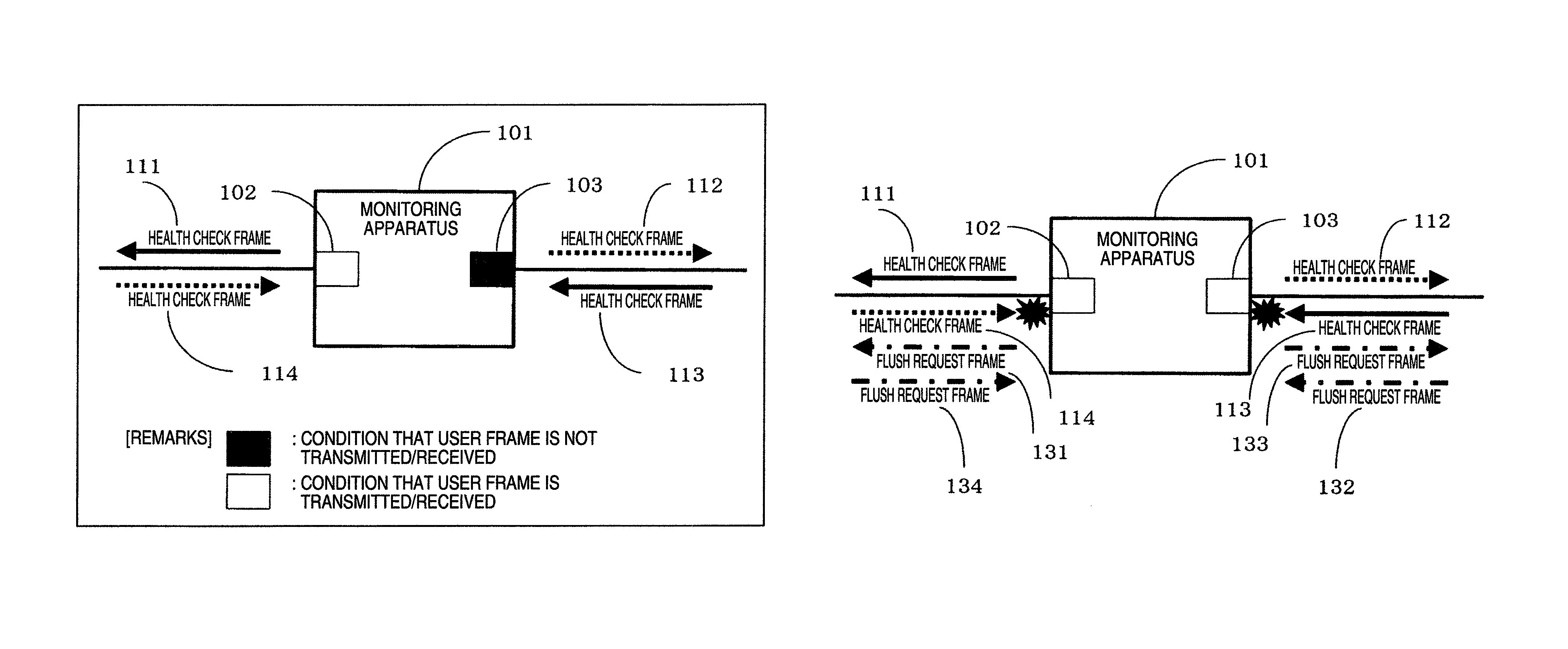
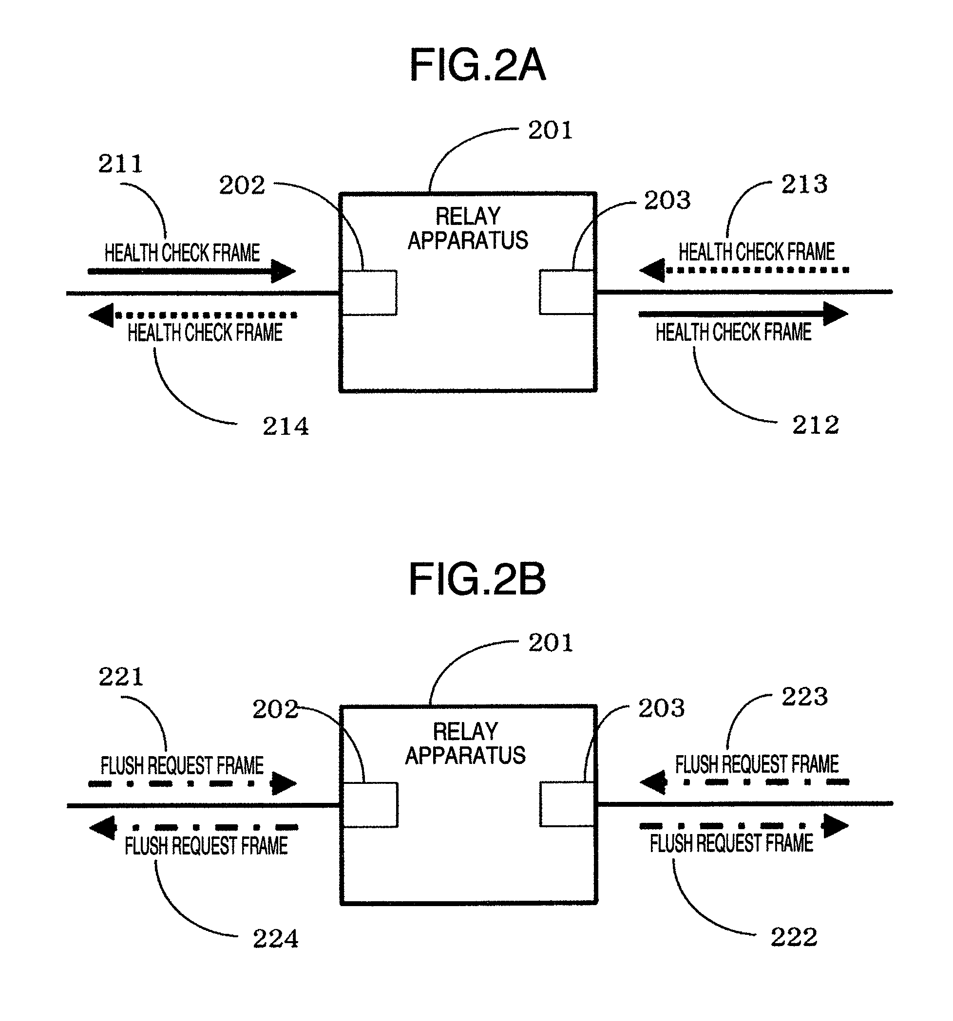
[0027]FIG. 1A and FIG. 1B schematically show an apparatus 101 (will be referred to as “monitoring apparatus” hereinafter) which monitors a ring network employed in a ring network constructing apparatus according to an embodiment of the present invention. The monitoring apparatus 101 constitutes a portion of a ring network indicated, for example, in FIG. 6, and corresponds to an apparatus 601 which monitors this ring network. The ring network is arranged by the monitoring apparatus 601 and other relay apparatuses 602, 603, and 604. Although a detailed description as to FIG. 6 will be made later, in this example, for instance, operations of the monitoring apparatus 601 in the ring network of FIG. 6 are described with reference to FIG. 1A and FIG. 1B. The monitoring apparatus 101 contains two pieces of ports (will be referred to as...


PUM


Abstract

As apparatuses which construct a ring network, a structure including a monitoring apparatus and other relay apparatuses is employed. The monitoring apparatus monitors only a ring status of such a ring network to which the own monitoring apparatus belongs. The monitoring apparatus periodically transmits health check frames from ring ports thereof respectively so as to monitor whether or not the transmitted health check frame has been received by the ring port located opposite thereto. Also, in a structure of a multi-ring network having a shared link, auxiliary health check frames are periodically transmitted from two sets of shared apparatuses respectively with respect to a monitoring apparatus of a shared link non-monitored ring network. The monitoring apparatus also monitors the auxiliary health check frames in combination with the health check frames in order to avoid an occurrence of a loop which bridges a plurality of ring networks.

Description

BACKGROUND OF THE INVENTION[0001]1. Field of the Invention[0002]The present invention generally relates to an apparatus which provides redundancy of communication routes in a ring network. More specifically, the present invention is directed to such an apparatus capable of realizing high-speed switching of routes, and capable of simply coupling a plurality of ring networks, and also capable of independently performing operations in each of these ring networks so as to realize constructions of more flexible networks, and further, capable of reducing loads given to a CPU.[0003]2. Description of the Related Art[0004]While networks are constructed, there are some possibilities that a plurality of apparatuses are connected to each other in ring structures in order to make communication routes redundant. Networks having ring structures have a feature that necessary amounts of transfer routes and the like may be reduced, as compared with those of networks having mesh structures. On the oth...

Claims


Application Information

Patent Timeline
Patent Type & Authority Patents(United States)
IPC IPC(8): G06F15/16G06F15/173H04L49/111
CPCH04L12/437H04L43/10H04L43/0805H04L49/30H04L25/20H04L43/0823H04L43/0876
Inventor SAKURAI, HIROTO
Owner ALAXALA NETWORKS
Learn More