Phase difference calibrating system for rotating shaft

A technology for calibrating systems and rotating shafts, applied in the direction of force/torque/work measurement instrument calibration/testing, measuring devices, instruments, etc., and can solve problems such as phase difference, no standard input signal, and inability to perform calibration

Inactive Publication Date: 2011-11-23
ZHONGBEI UNIV
View PDF2 Cites 11 Cited by
  • Summary
  • Abstract
  • Description
  • Claims
  • Application Information

AI Technical Summary

Problems solved by technology

However, this kind of device or instrument has no standard input signal during circuit debugging, especially the phase difference in the case of rotation, so it cannot be calibrated

Method used


Image

  • Phase difference calibrating system for rotating shaft
  • Phase difference calibrating system for rotating shaft
  • Phase difference calibrating system for rotating shaft

Examples


Embodiment 1

[0019] Embodiment 1. Rotary axis calibration system

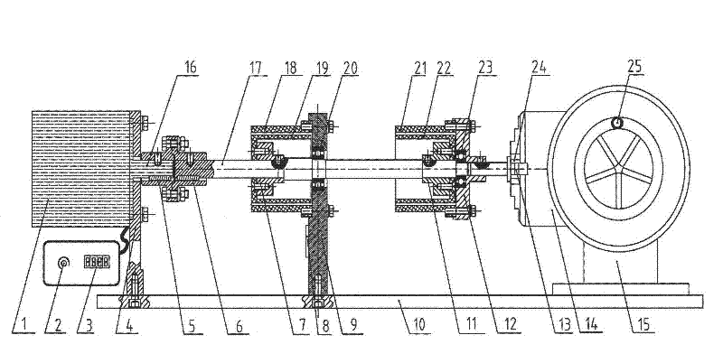
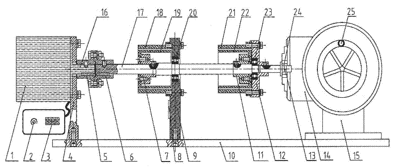
[0020] This rotating shaft calibration system of this example is used to calibrate the instrument or device for measuring the rotational speed of the rotating shaft, and the specific structure of the rotating shaft rotational speed calibration system can be figure 1 As shown, the calibration system includes: a motor 1 and its driven motor shaft 16, the front end of the rotating shaft motor shaft 16 and the rotating shaft 17 are connected on the coaxial line through a coupling 5-6. The bracket 9 that fixes the rotating shaft 17, the middle part of the rotating shaft 17 is rotatably arranged or installed on the bracket 9 such as through the bearing A (20). Sleeve A is also installed on the support 9, and sleeve A is made up of the urceolus A (18) that is installed on the support 9 and the inner cylinder A (19) that is installed on the rotating shaft 17 by follower sleeve A (7). The part to be calibrated in this example is th...

Embodiment 2

[0023] Embodiment 2. Rotary axis calibration system

[0024] The structure of the rotary axis calibration system in this example can generally be used figure 1 As shown, the structure of the calibration system is as described in Embodiment 1 and will not be repeated. The difference between the rotary shaft speed calibration system of this example and the rotary shaft speed calibration system of Embodiment 1 is as follows: 1. The instrument or device for measuring the rotary shaft speed of the calibrated part of the rotary shaft speed calibration system of this example is a grating rotary shaft speed Tester, the structure of the grating rotary shaft speed tester is composed of a light source A, a grating A, a photoelectric receiving element A, a counting circuit and a display circuit. The grating A is installed on the rotating shaft 17 coaxially with the rotating shaft 17, and the light source A and the photoreceiving element A are arranged on one side of the grating A (for th...

Embodiment 3

[0025] Embodiment 3. Rotary axis calibration system

[0026] The structure of the rotary axis calibration system in this example can generally be used figure 1As shown, the structure of the calibration system is as described in Embodiment 1 and will not be repeated. The difference between the rotary shaft speed calibration system of this example and the rotary shaft speed calibration system of embodiment one and embodiment two is: 1. The instrument or device for measuring the rotary shaft speed of the calibrated part of the rotary shaft speed calibration system of this example is Hall rotary shaft speed tester, the structure of the Hall rotary shaft speed tester is composed of magnets, Hall sensors, counting circuits and display circuits and other test circuits. Stick the magnet on the rotating shaft 17, and the probe of the Hall sensor is aligned with the magnet and installed on the bracket 9. The output end of the hall sensor is connected with the input end of the counting...


PUM


Abstract

The invention discloses a phase difference calibrating system for a rotating shaft, comprises two technical schemes and belonging to the technical field of surveying or metrology, wherein one technical scheme is a rotating-shaft rotating speed calibrating system for calibrating a device used for measuring the rotating shaft rotating speed, and the other technical scheme is a rotating-shaft phase difference calibrating system for calibrating a device used for measuring the phase difference of the rotating shaft. The technical schemes disclosed by the invention have the advantages that: the calibrating system is beneficial to overcoming of the defects that the rotating speed and phase difference (torque) testers cannot be calibrated in the prior art, supplies a calibrating device and calibrating precisions thereof for the rotating speed and phase difference (torque) testers of the rotating shaft, has practical significance, and can be used for calibrating the rotating-shaft rotating speed testers, such as a capacitive grating, an optical grating, a Hall sensor, a magnetic grating, an infrared device, a photoelectric device, a photoelectric encoder and the like, and the rotating-shaft phase testers, such as a capacitive grating, an optical grating, a magnetic grating and the like. The calibrating system disclosed by the invention has a simple and flexible structure, convenience for operation and wide application range, the rotating speed of the rotating shaft is adjustable, sleeves are replaceable and the distance between every two sleeves is also adjustable.

Description

1. Technical field [0001] The rotating shaft phase difference calibration system disclosed by the invention belongs to the technical field of measurement or measurement, and specifically relates to a calibration system for calibrating and measuring the rotation speed and phase difference (or even torque) system of a rotating shaft. 2. Background technology [0002] In industrial production, scientific research, and daily life, the measurement of speed and torque has been very extensive. In many cases, it is necessary to test the torque value while the shaft is rotating. For example, the shaft torque test system based on the capacitive sensor can be applied to the rotating shaft. The speed and torque test, the test principle is to paste two sets of capacitive grid sensors on the two ends of the shaft respectively, use the periodic change of the differential capacitor grid capacitance, and process it through the differential pulse width modulation circuit and the low-pass filte...

Claims


Application Information

Patent Timeline
Patent Type & Authority Applications(China)
IPC IPC(8): G01P21/02G01L25/00
Inventor 靳鸿马铁华张红艳张艳兵裴东兴王燕沈大伟刘飞付永乐
Owner ZHONGBEI UNIV
Why Eureka
Try Eureka