Containment system for oil field riser pipes

Inactive Publication Date: 2012-09-04
DESLIERRES JOHN MAYN +1
View PDF1 Cites 14 Cited by
  • Summary
  • Abstract
  • Description
  • Claims
  • Application Information

AI Technical Summary

Benefits of technology

[0002]The object of this invention is to provide an urgent means for stopping and capping oil/gas escaping passage uncontrollably up a riser tu

Problems solved by technology

What was feasible originally for the establishment and plugging of these test well sites, in shallow water, has become more difficult when encountering extremely high pressures, and the methods for plugging these wells have become risky and coping with this immense high pressure, is the reason why these previous methods of plugging wells have now been considered dangerous and almost impossible to accomplish.
Because of this condition, there have been times when accidents have happened at these well sites resulting in great quantities of oil dispersed in the ocean.
In a few occasions, operating personal lost their lives while closing down the well sites.
The system of pumping cement down the riser is next to impossible where well pressures are up in the thousands.
A rec

Method used


Image

  • Containment system for oil field riser pipes
  • Containment system for oil field riser pipes
  • Containment system for oil field riser pipes

Examples


Example

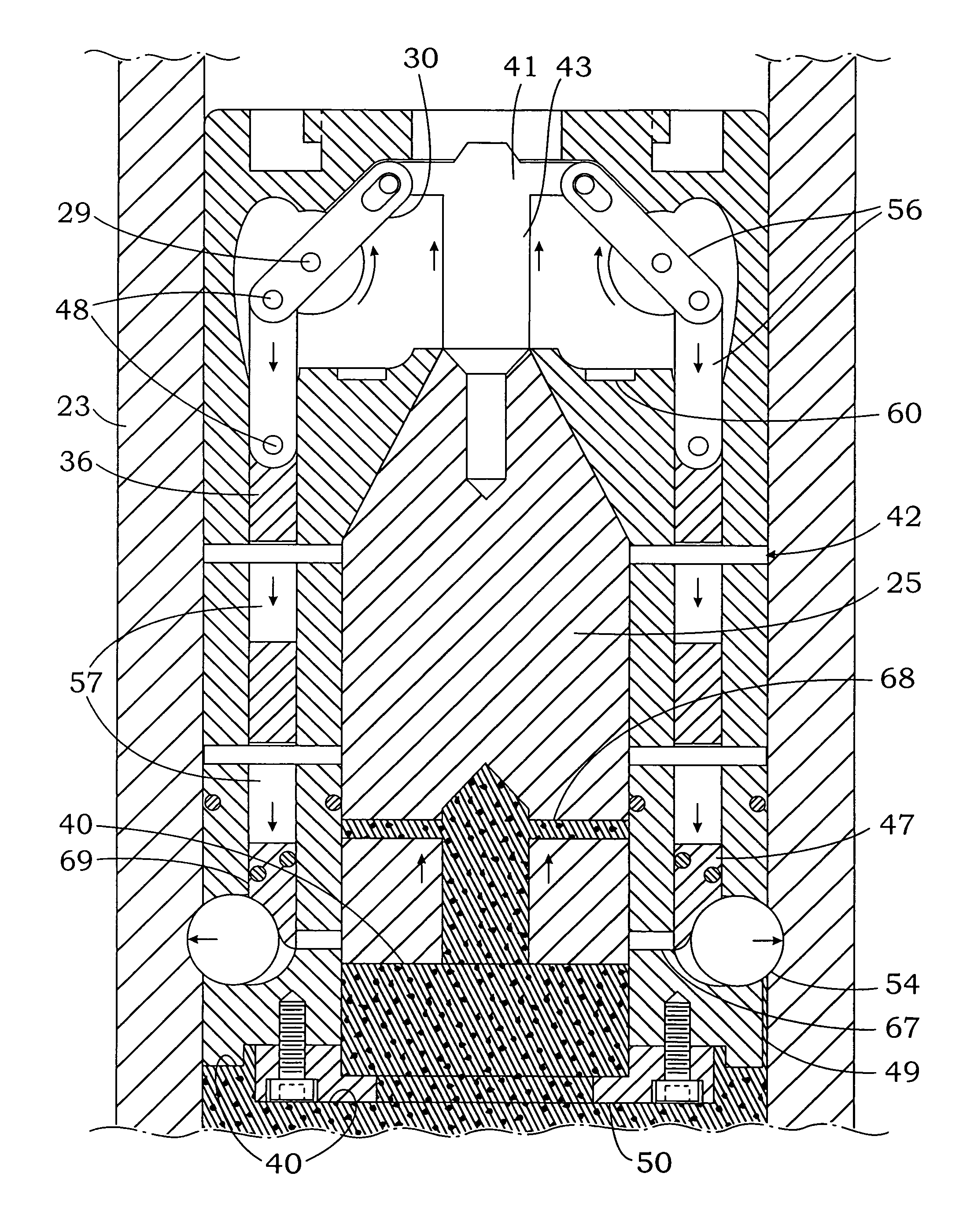
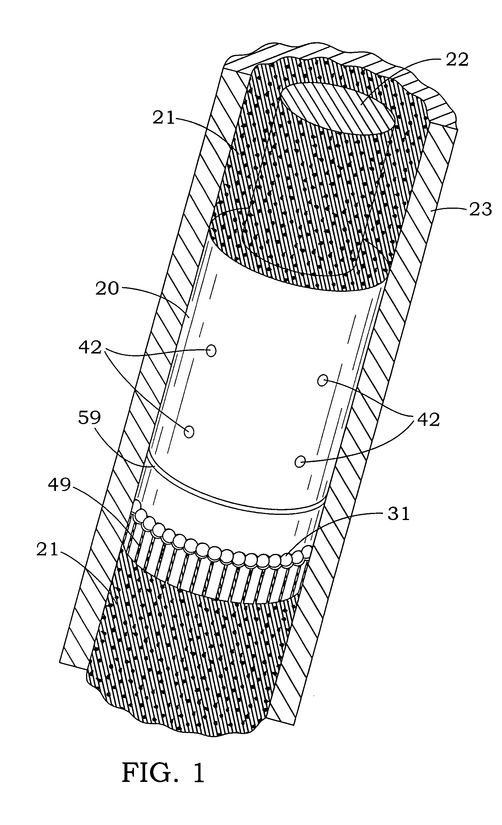
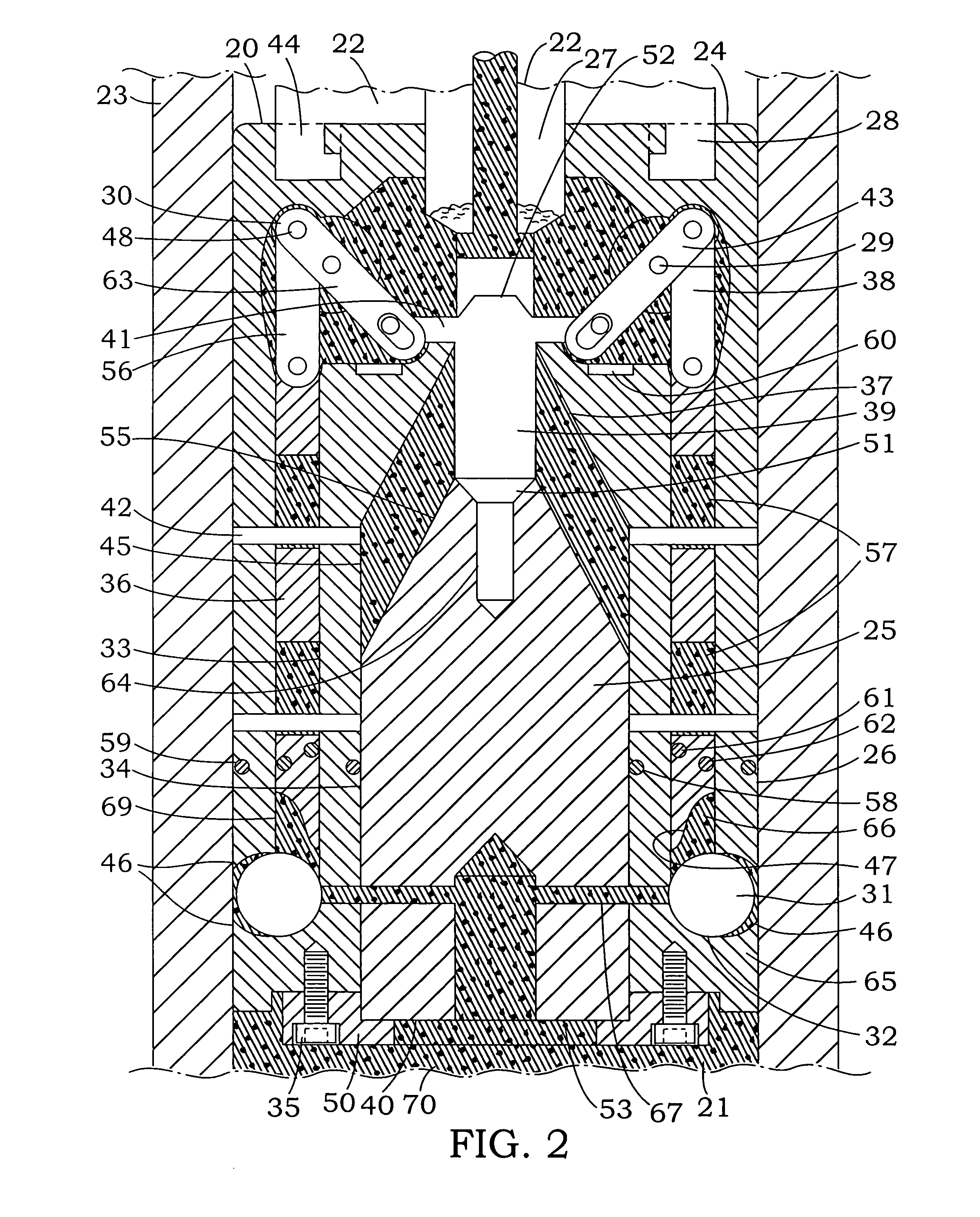
[0039]The instant invention is an oil retention system designed to be inserted into the riser pipe and moved downward by the use of the extension post of the drill string engagement tool (22), at the ocean surface on the drill ship, platform or operating unit. The invention provides a means for plugging the well riser pipe (23) with an oil / gas riser containment valve (20) which has on its outside structure (66) short vertical grooves (49) to be attached to the end of the drill string engagement tool (22) and inserted down the riser pipe (23), and it releases a sealing stop flow plug (25) to stop the flow of oil / gas (21) coming up the riser pipe from the newly drilled well. This riser containment valve (20) is driven to the close position by the internal pressure within the riser pipe (23). This means that the containment valve (20) can operate and shut off the pressure anywhere down the riser pipe (23), as desired. The containment valve (20) engages the end of the drill string tool ...


PUM


Abstract

A riser pipe containment valve attached to the drill string tool that uses the wells' intense pressure to cap and control flow when lowered down the riser and attached to its internal wall. Oil/gas sealing and stoppage flow through the valve are controlled by stop flow plug movement. The valve attached then to the riser pipe wall is locked to that surface with pressure indented balls forced into wall indented cavities locking valve to riser in multiple engagement points. When the valve is installed as a riser pipe insert, and used as a by-pass stop flow pipe, without retention attachments, it continues to function as an oil/gas stop flow plug system, and electronic sensors in the valve are utilized to monitor flow and sealing conditions relative to high pressure and convey data to the drill string tool and its electronic system display.

Description

FIELD OF THE INVENTION[0001]This invention relates generally to offshore monitoring and control of oil / gas from new and / or existing wells previously drilled and in the recoverable mode, mainly when out of control and intense pressures are encountered.THE OBJECT OF THE INVENTION[0002]The object of this invention is to provide an urgent means for stopping and capping oil / gas escaping passage uncontrollably up a riser tube and providing a means to inhibit the tremendous loss of product and its damage to the environment, mainly when other capping procedures fail.[0003]PRIOR ART—REFERENCES CITED—2,570,372Oct. 9, 1951Parrish(137 / 88)3,783,887Jan. 8, 1974Shoji(137 / 38)4,126,183Nov. 21, 1978Walker(166 / 338, 337, 364, 72)4,813,495Mar. 21, 1989 Leach(175 / 6, 166 / 358, 175 / 7)5,727,640Mar. 17, 1998Gleditsch(175 / 7, 166 / 358)6,401,823 B1Jun. 11, 2002Gonzalez et al (166 / 319, 321)6,668,943 B1Dec. 30, 2003Maus et al(175 / 5, 25, 38, 48, 212)6,802,379 B2Oct. 12, 2004Dawson et al(175 / 38, 70, 206)2005 / 0284639 ...

Claims


Application Information

Patent Timeline
IPC IPC(8): E21B21/10
CPCE21B17/01E21B34/04E21B34/00E21B33/02
Inventor DESLIERRES, JOHN MAYNCABEDO-DESLIERRES, MARIA R.
Owner DESLIERRES JOHN MAYN
Why Eureka
Try Eureka