
Method and device for tear film analysis

a technology of tear film and analysis method, applied in the field of non-invasive methods and devices, can solve the problems of subjective and unquantified information, difficult to analyze the quality and dynamics of tear film, and difficult to align, etc., and achieve the effect of simple structure, convenient alignment and portability

Active Publication Date: 2012-09-04
RGT UNIV OF CALIFORNIA
View PDF2 Cites 5 Cited by
  • Summary
  • Abstract
  • Description
  • Claims
  • Application Information

AI Technical Summary

Benefits of technology

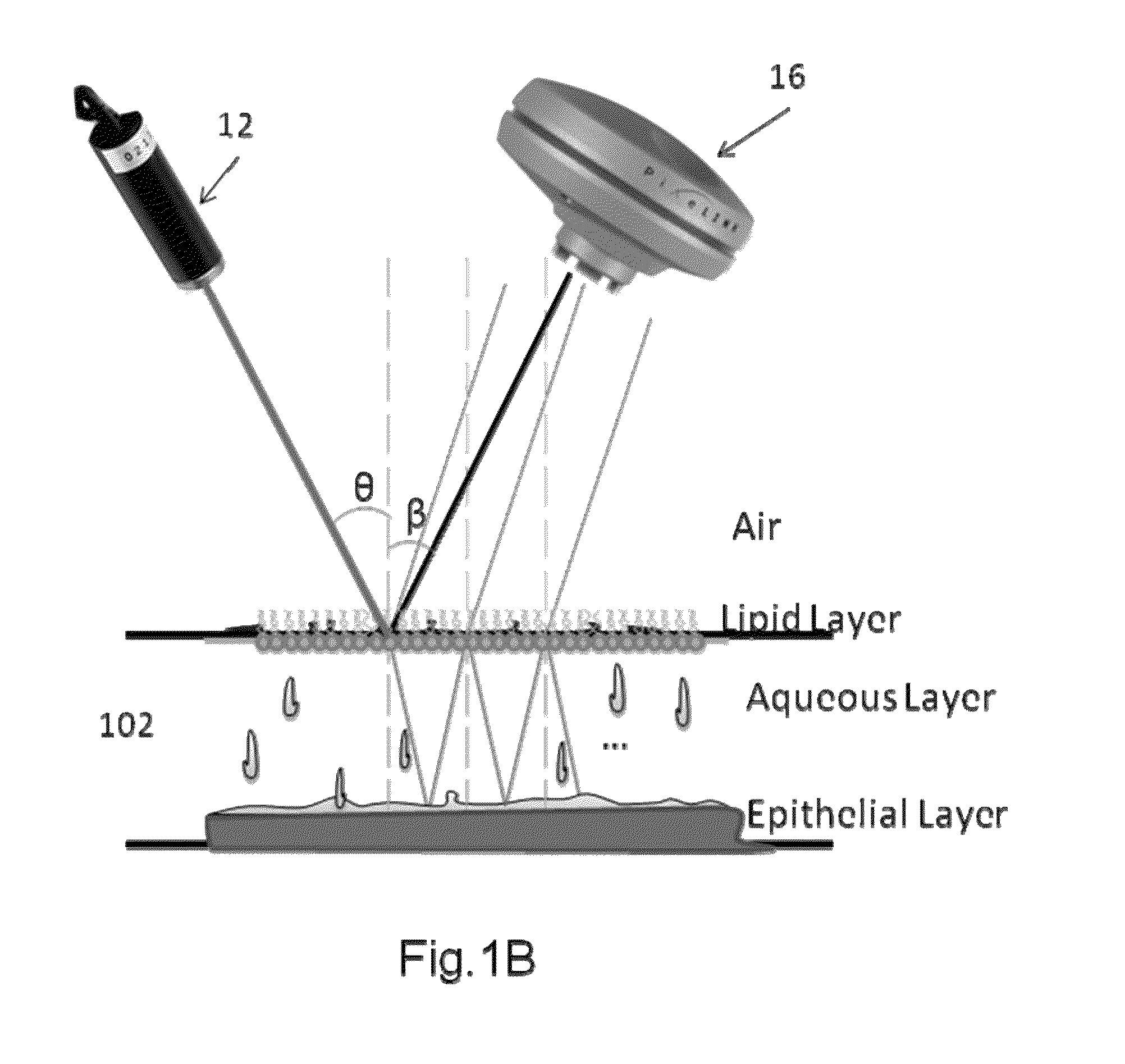
The invention is a non-invasive method for evaluating the thickness and spatial features of the ocular tear film using Fluctuation Analysis of Spatial Image Correlation (FASIC) by applying the basis of spatial autocorrelation technique. This technique allows for the quantitative assessment of the spatial fluctuations in a series of images and the thickness information can be obtained by calculating spatial autocorrelation in the raw camera images. The invention provides a robust, portable, low-cost, and easy-to-align system and method for evaluating the tear film.

Problems solved by technology

Analyzing the tear film quality and dynamics are complex tasks.
The most commonly used diagnostic methods, such as the Schirmer test, Rose Bengal, and fluorescein staining, are invasive and can be uncomfortable for the patient.
These techniques are subjective and do not provide quantitative information.
However, these techniques have not been applied routinely yet.
However, OCT generally does not have the resolution in the axial direction to directly measure the tear film.

Method used


Image

  • Method and device for tear film analysis
  • Method and device for tear film analysis
  • Method and device for tear film analysis

Examples


Embodiment Construction

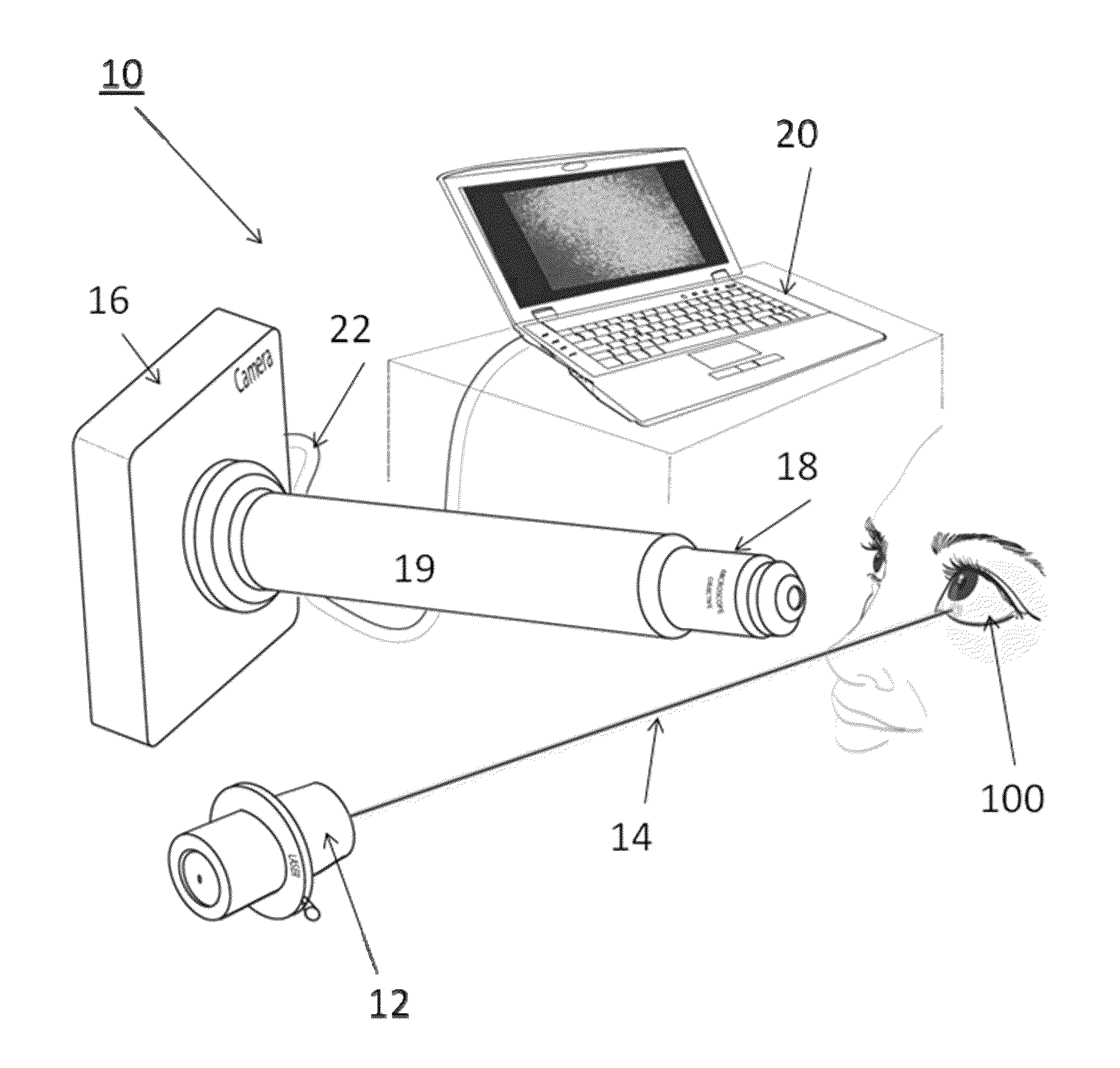
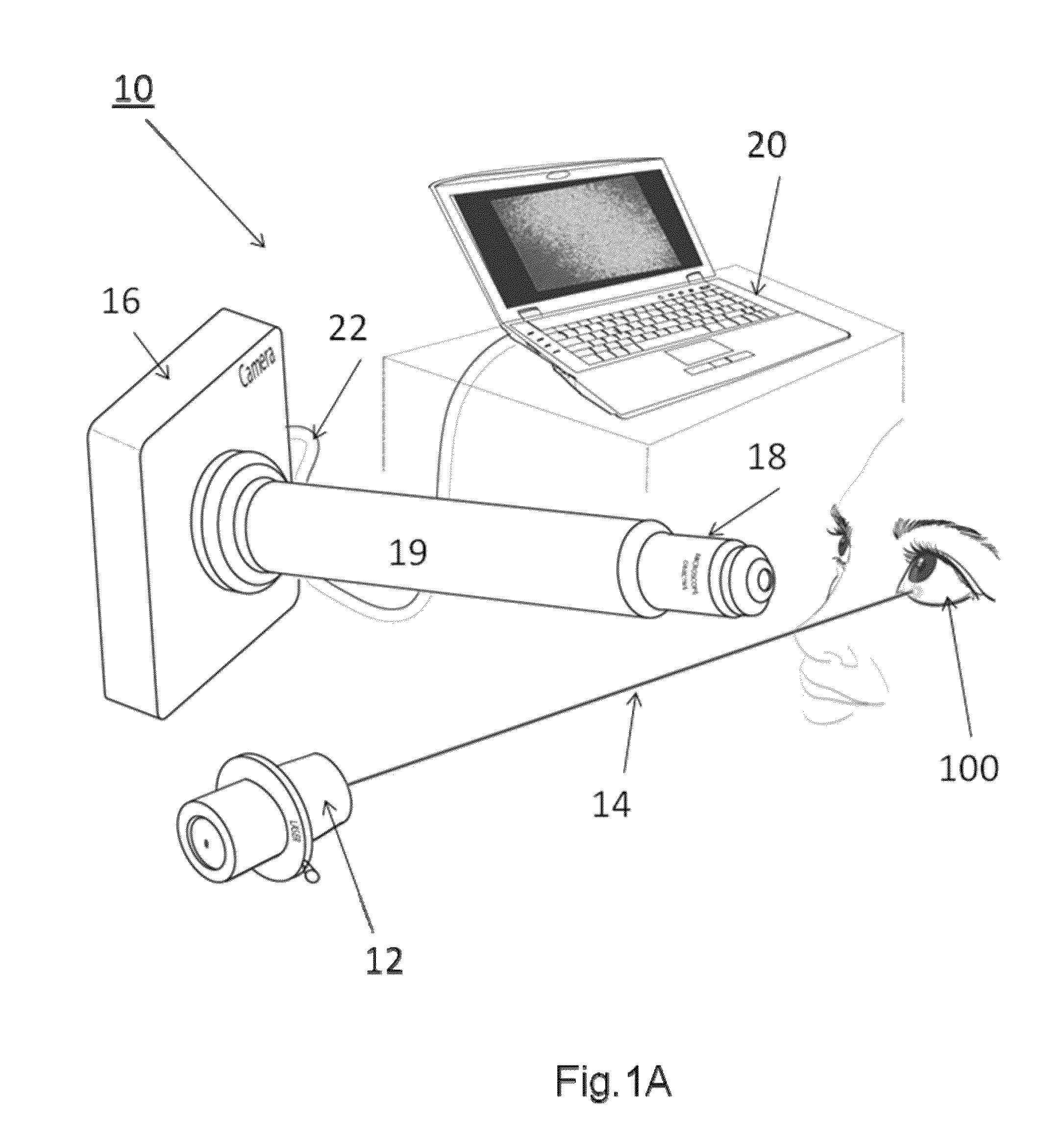
[0030]A schematic of the imaging system 10 is illustrated in FIG. 1A. The imaging system 10 generally includes an illumination source 12 that is used to direct radiation 14 onto the surface of the eye 100. The illumination source 12 may include a laser or light emitting diode (LED). The laser may have a narrow wavelength range or, alternatively, the laser may include a white or broadband wavelength. In the later case, the broader wavelength range can provide additional information on the components and physical features of the tear film. In yet another alternative, two or more lasers (or LEDs) may be used with each laser (or LED) having a different wavelength. Multiple wavelengths would provide additional information on the components of the tear film.

[0031]As another alternative, a monochromatic LED may be used. The LED as a light source would remove the speckles. With a monochromatic LED, one would only need to analyze the interference pattern. In still another alternative, a broa...


PUM


Abstract

Tear film stability has an important role in the quality of vision. A system and method for performing Fluctuation Analysis of Spatial Image Correlation (FASIC) provides for a non-invasive system and method for evaluating the dynamics of the tear film surface using spatial autocorrelation analysis. With FASIC, a series of images are obtained using illumination and a camera. The spatial autocorrelation is calculated for image frames produced by the camera. A sinusoidal background appears in this correlation together with other features. The changes in the sinusoidal background of the spatial autocorrelation is extracted and monitored over time. The spatial period of this sinusoidal background correlates with the thickness of the tear film. In this regard, one is able to derive the tear film thickness from the period of this sinusoidal background.

Description

RELATED APPLICATION[0001]This application claims priority to U.S. Provisional Patent Application No. 61 / 186,767 filed on Jun. 12, 2009. U.S. Patent Application No. 61 / 186,767 is incorporated by reference as if set forth fully herein. Priority is claimed pursuant to 35 U.S.C. §119 and any other applicable statute.STATEMENT REGARDING FEDERALLY SPONSORED RESEARCH OR DEVELOPMENT[0002]This invention was made with Government support under Grant No. RR003155, awarded by the National Institutes of Health. The Government has certain rights to this invention.FIELD OF THE INVENTION[0003]The field of the invention generally relates to non-invasive methods and devices used to analyze the ocular tear film. More specifically, the field of the invention pertains to devices and methods that rely on or use the spatial autocorrelation of a two dimensional laser speckle and interference pattern to quantify the tear film thickness and / or its morphological features.BACKGROUND OF THE INVENTION[0004]Tears ...

Claims


Application Information

Patent Timeline
Patent Type & Authority Patents(United States)
IPC IPC(8): A61B3/14A61B3/10
CPCA61B3/101
Inventor GRATTON, ENRICOAZARTASH, KAVEHMARSILI, LUISA
Owner RGT UNIV OF CALIFORNIA
Learn More