Vehicle reflector and reflex pin

a technology of reflector and reflex pin, which is applied in the direction of optics, instruments, optical elements, etc., can solve the problems of increasing manufacturing error, and achieve the effects of enhancing the luminous intensity in the observation angle direction, good end result, and increasing manufacturing error

Active Publication Date: 2012-09-04
STANLEY ELECTRIC CO LTD
View PDF3 Cites 0 Cited by
  • Summary
  • Abstract
  • Description
  • Claims
  • Application Information

AI Technical Summary

Benefits of technology

[0009]In the vehicle reflector 210 described in Japanese Patent No. 3340640, the luminous intensity in the observation angle θ direction is enhanced. However, not only are the respective inclination angles of the first reflection surface to the third reflection surface adjusted with respect to the reference angle AX, but also the respective rotational angles β and γ of the second reflection surface and the third reflection surface are typically adjusted to achieve a good end result in this product. Therefore, there arises a problem in that the number of items to be adjusted increases, and manufacturing error therefore can increase, which can influence quality of finished products.
[0012]In the above described aspect of the presently disclosed subject matter, the rotational angles of the second reflection surface and the third reflection surface with the reference axis as the center are set at 120°. Therefore, by only setting practically three parameters (α1, α2, α3) so as to satisfy the relation of −α1=α2=α3 (or −α1≈α2=α3) without adjustment of the respective rotational angles β and γ of the second reflection surface and the third reflection surface, which has been conventionally required, the luminous intensity in the observation angle direction can be equivalent to or higher than the above-described conventional reflector. More specifically, according to the first aspect of the presently disclosed subject matter, adjustment of the respective rotational angles β and γ of the second reflection surface and the third reflection surface is not required, although the adjustment of the angles β and γ has been conventionally required. Therefore, the number of items for adjustment decreases, and manufacturing errors can be reduced, so that quality of the finished products can be increased.
[0014]According to the second aspect of the presently disclosed subject matter, the respective rotational angles of the second inclined surface and the third inclined surface with the center axis of the reflex pin as the center are set at 120°. Therefore, the reflex pin can be formed, which is used for formation of the vehicle reflector which can realize the luminous intensity in the observation angle direction which is equivalent to or higher than the conventional reflector by only setting practically three parameters (α4, α5, α6) so as to satisfy the relation of −α4=α5=α6 (or −α4≈α5=α6) without adjustment of the respective rotational angles β and γ of the second inclined surface and the third inclined surface, although the adjustment of the angles β and γ has been conventionally required. More specifically, according to the second aspect of the presently disclosed subject matter, adjustment of the respective rotational angles β and γ of the second inclined surface and the third inclined surface is not required, although the adjustment of the angles β and γ has been conventionally required. Therefore, the number of items for adjustment decreases, and manufacturing errors can be restrained, so that quality of the finished products can be increased.

Problems solved by technology

Therefore, there arises a problem in that the number of items to be adjusted increases, and manufacturing error therefore can increase, which can influence quality of finished products.

Method used


Image

  • Vehicle reflector and reflex pin
  • Vehicle reflector and reflex pin
  • Vehicle reflector and reflex pin

Examples


Embodiment Construction

[0032]Hereinafter, an example of a vehicle reflector which is one embodiment of the presently disclosed subject matter will be described with reference to the drawings.

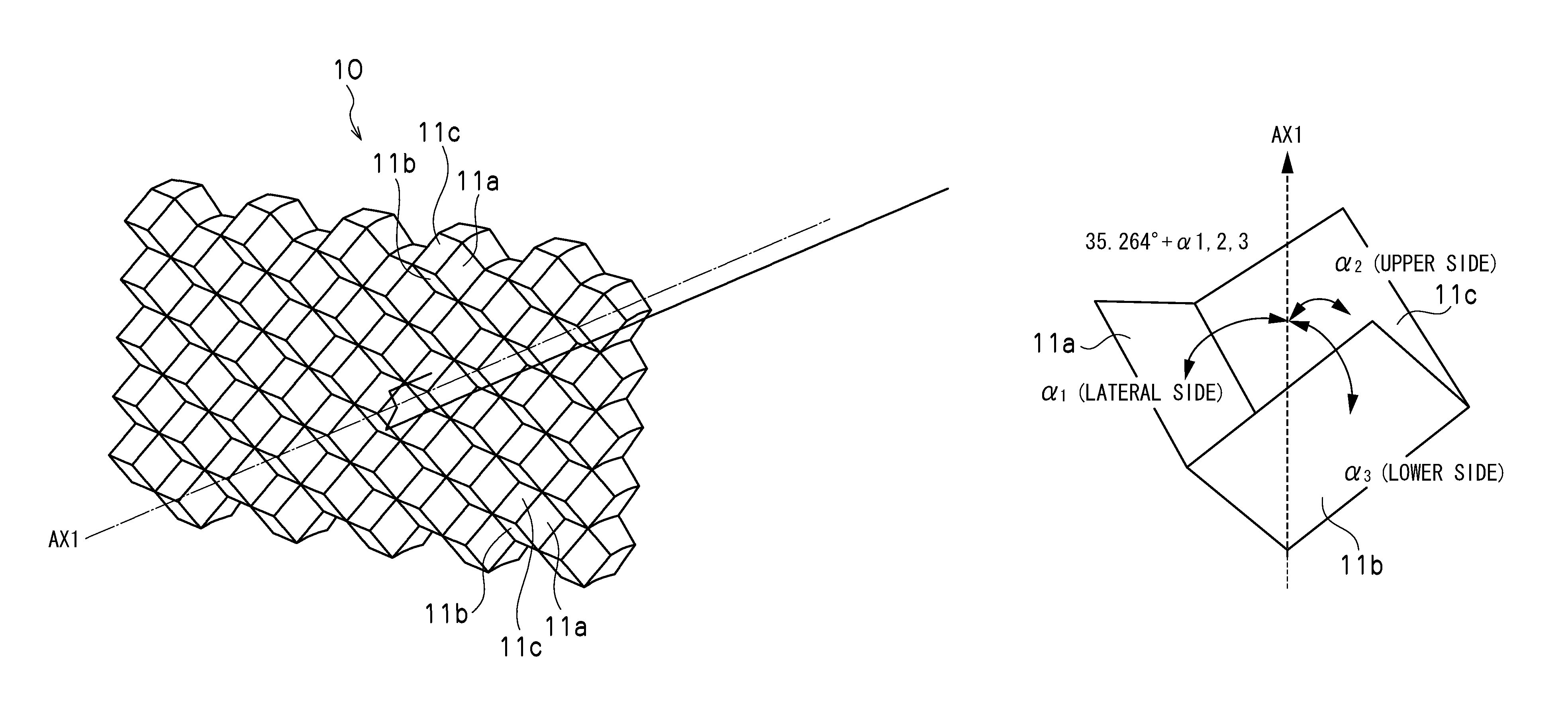
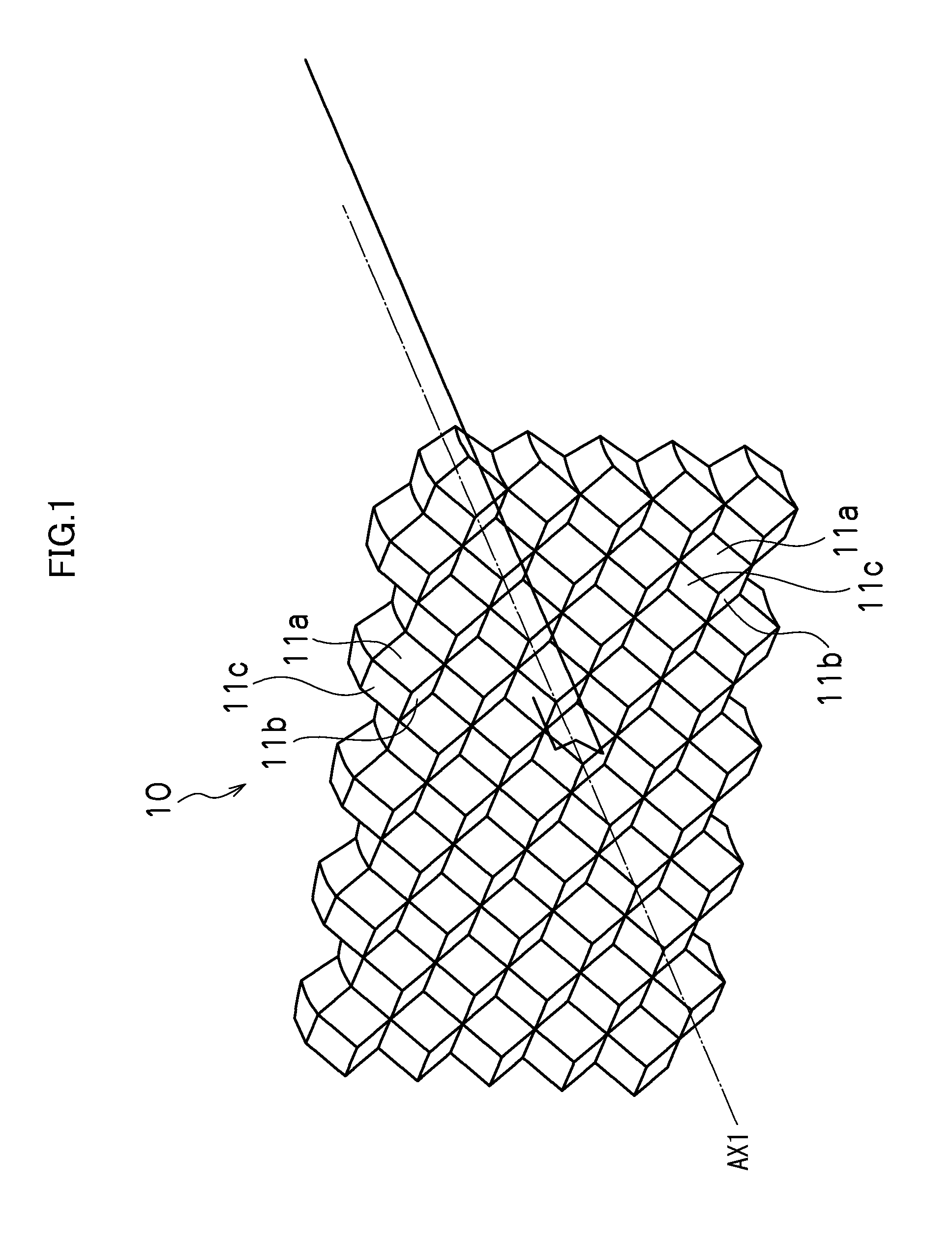
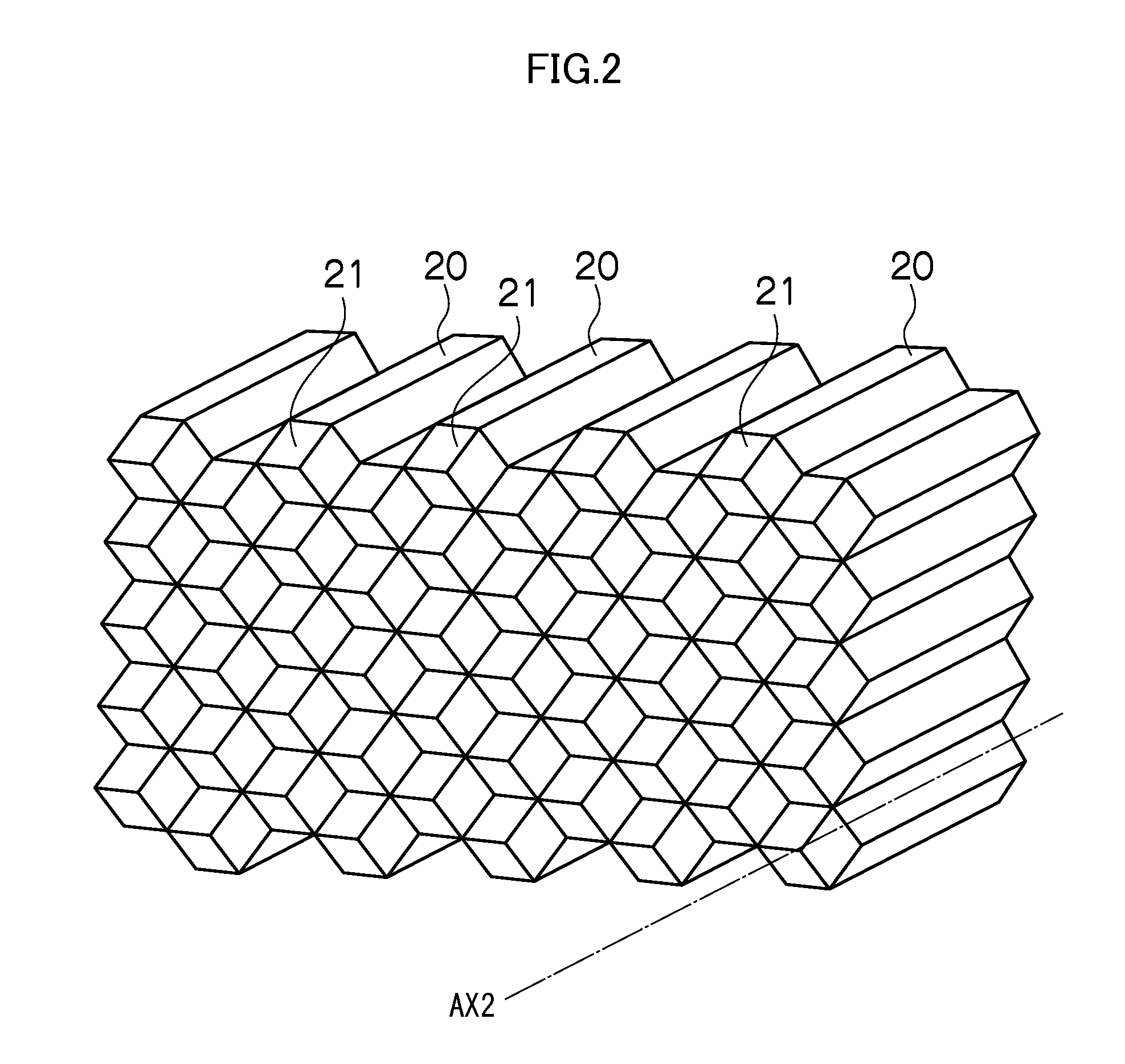
[0033]A vehicle reflector 10 of the present embodiment is a so-called reflex reflector which is fitted to a vehicle, such as an automobile, a two-wheeler, a truck, an SUV, etc. As illustrated in FIG. 1, the vehicle reflector 10 can include a front surface on which irradiated light from other vehicles, exterior lights, and the like located around the vehicle to which the vehicle reflector 10 is attached is incident, a back surface on an opposite side of the front surface, and a plurality of retroreflection elements 11 which are defined by a plurality of reflex pins 20 (tip end portions 21) as illustrated in FIG. 2 on the back surface. The vehicle reflector 10 can be formed by a light transmissive material such as acryl and polycarbonate such as in an ordinary reflex reflector.

[0034]The retroreflection element 11 can in...


PUM


Abstract

A vehicle reflector can include a plurality of retroreflection elements including a first reflection surface, a second reflection surface, and a third reflection surface which are adjacently disposed to form a corner portion of a substantially regular hexahedron. The first reflection surface can be inclined by 35.264°+angle α1 with respect to a reference axis. The second reflection surface can be inclined by 35.264°+angle α2 with respect to the reference axis and can be disposed at a position rotated by 120° about the reference axis from the first reflection surface. The third reflection surface can be inclined by 35.264°+angle α3 with respect to the reference axis and can be disposed at a position rotated by 120° in an opposite direction from the second reflection surface about the reference axis from the first reflection surface. The angle α1, angle α2 and angle α3 can be set to satisfy a relation of −α1=α2=α3 or −α1≈α2=α3.

Description

[0001]This application claims the priority benefit under 35 U.S.C. §119 of Japanese Patent Application No. 2010-094197 filed on Apr. 15, 2010, which is hereby incorporated in its entirety by reference.BACKGROUND[0002]1. Field[0003]The presently disclosed subject matter relates to a vehicle reflector and a reflex pin, and particularly relates to a vehicle reflector capable of obtaining a luminous intensity in an observation angle direction which is equivalent to or higher than certain conventional reflectors by setting an inclination angle of each of the first reflection surface to the third reflection surface, and by using a reflex pin in formation of the vehicle reflector.[0004]2. Description of the Related Art[0005]In the field of vehicle reflectors, an increase in the luminous intensity in the observation angle direction has been demanded. And, as one example of a reflector that may respond to such demand, a vehicle reflector is described in, for example, Japanese Patent No. 3340...

Claims


Application Information

Patent Timeline
Patent Type & Authority Patents(United States)
IPC IPC(8): G02B5/124
CPCG02B5/122
Inventor NAKATANI, AKIHIRO
Owner STANLEY ELECTRIC CO LTD
Why Eureka
Try Eureka