Pad dresser, polishing device, and pad dressing method

a polishing device and pad dressing technology, applied in the direction of grinding drives, grinding drives, manufacturing tools, etc., can solve the problems of both sides being similarly worn out and decayed, the recovery rate of the removal rate is at most 31.4%, and the brush has no effect of cutting off the pad surface, etc., to achieve good polishing process and excellent uniform removal rate

Inactive Publication Date: 2012-09-04
TOKYO SEIMITSU
View PDF11 Cites 4 Cited by
  • Summary
  • Abstract
  • Description
  • Claims
  • Application Information

AI Technical Summary

Benefits of technology

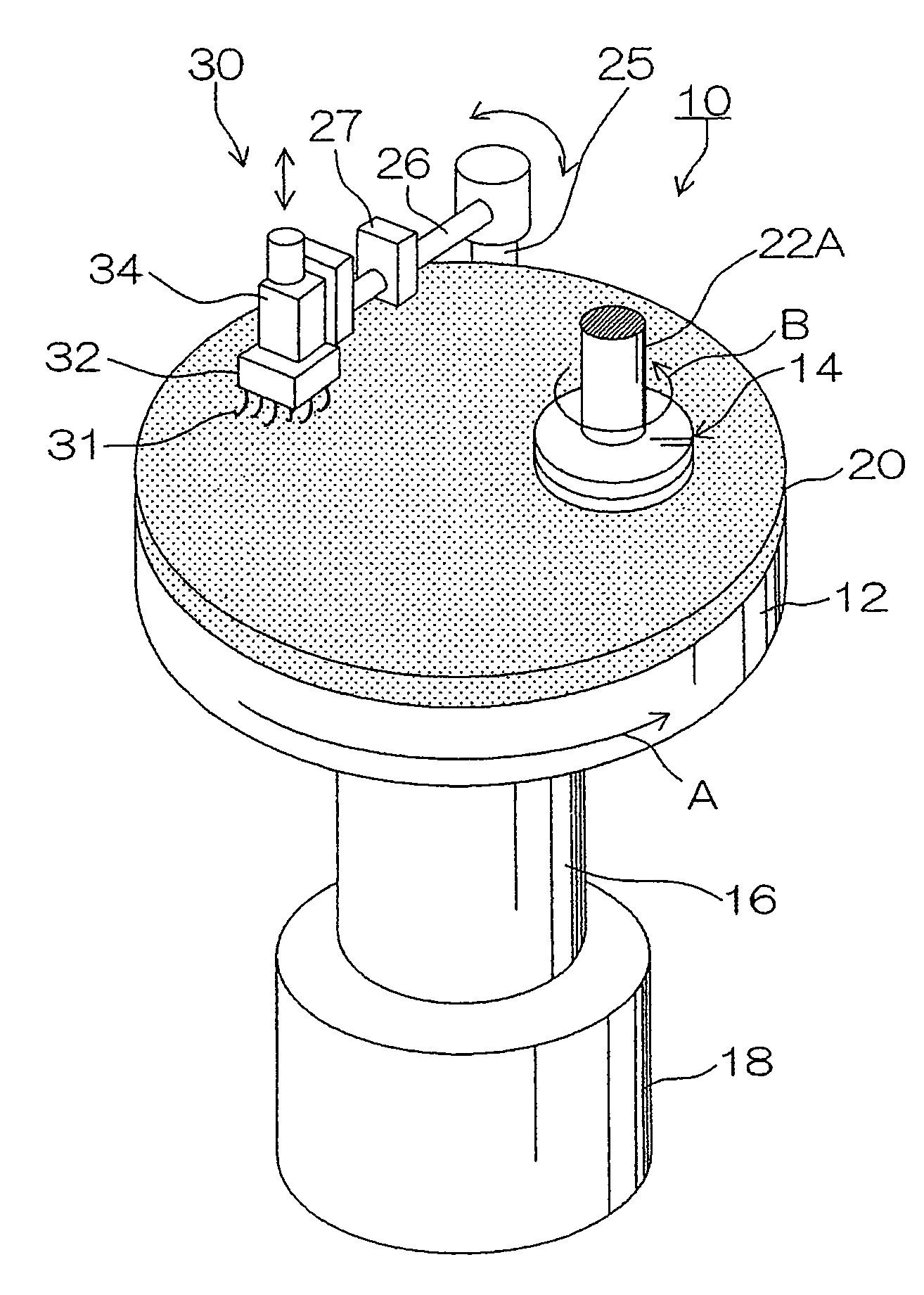
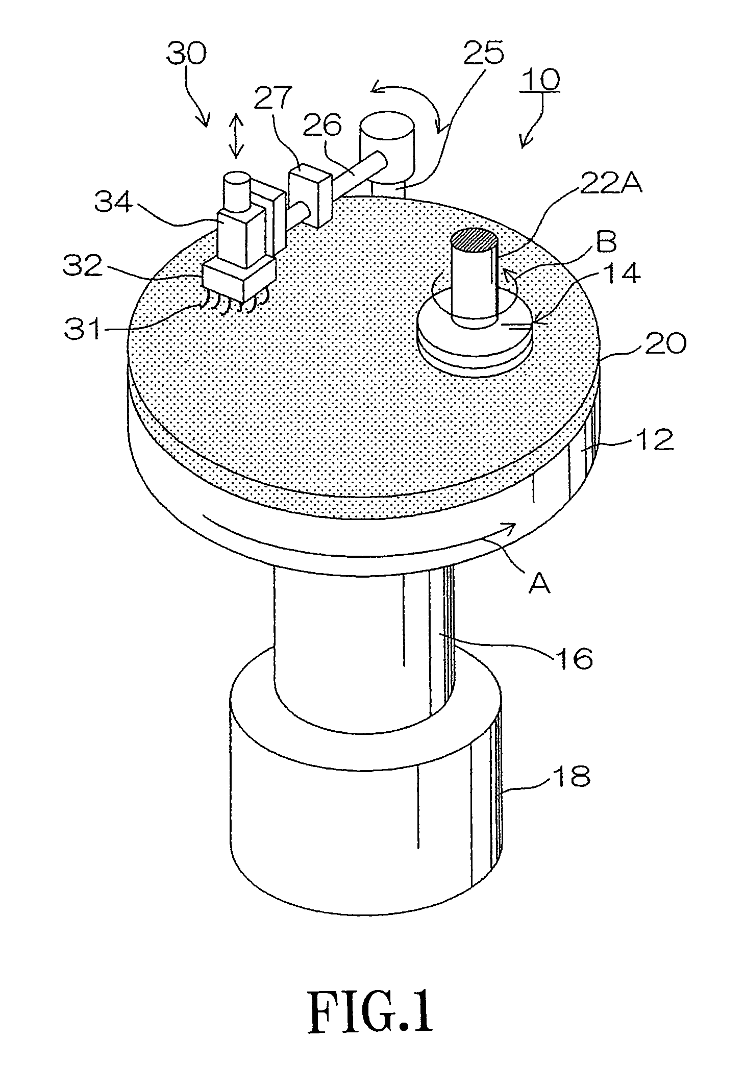
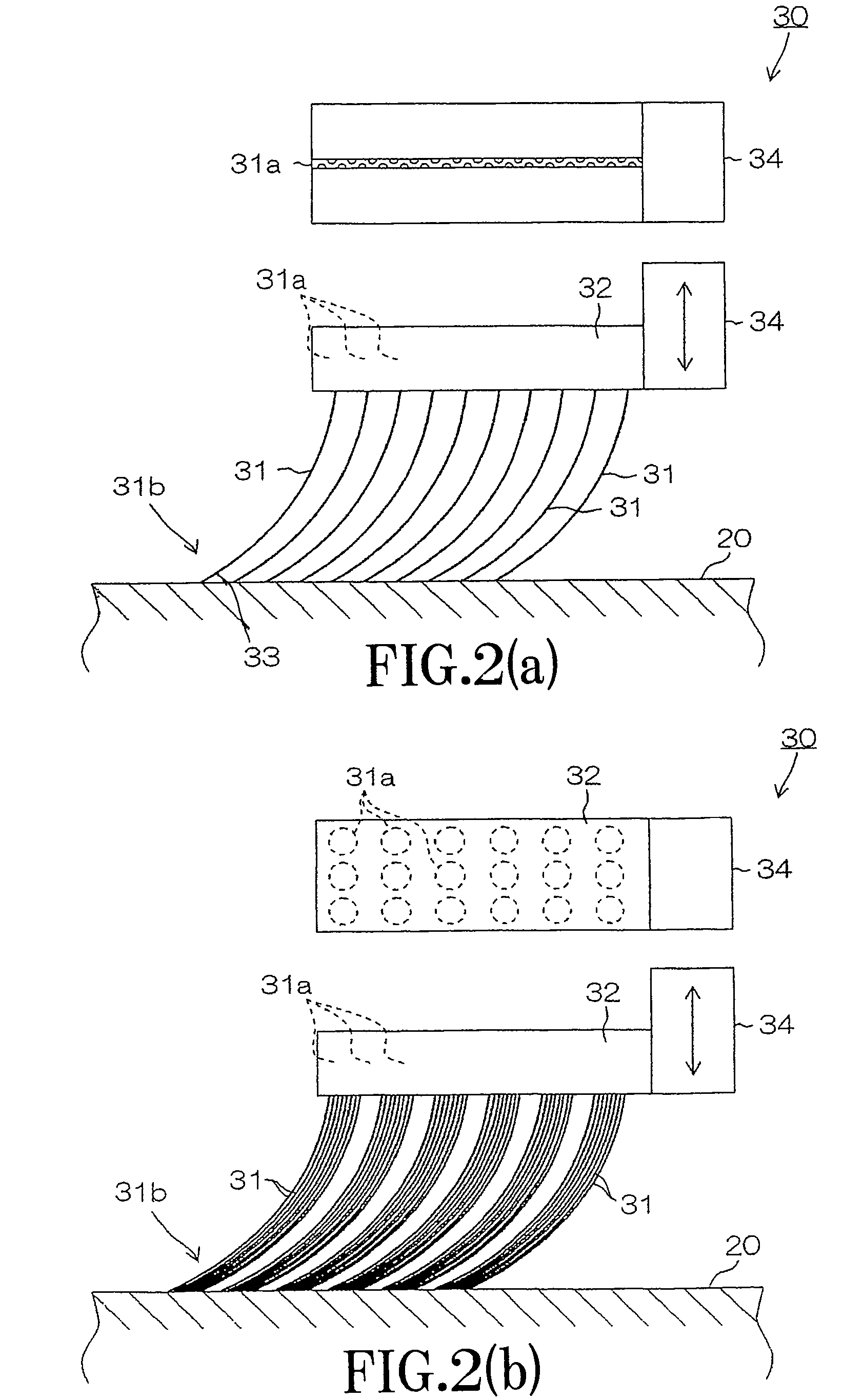
[0058]However, by the pad dresser according to an embodiment, the elastic deformation part of the elastic material which comprises a plurality of element wires performs elastic deformation under the state where the pad is fixed and supported on the platen, the tip part of the elastic material contacts the surface of the pad so as to follow the undulation of the surface of the pad. The tip part becomes able to perform dressing on the reference of the pad surface as a result by having the function to cut and roughen the pad.
[0083]According to another embodiment of the invention, since the uniform pad dressing along the surface of the polishing pad is possible, the good polishing process which is excellent in uniformity of the removal rate of the in-surface of the work can be performed.

Problems solved by technology

However, although the nylon brush has an ability to brush the pad surface, the brush has no effect of cutting off the pad surface.
However, in spite of prolonged pure-water feed and brushing, the recovery of the removal rate was at most only 31.4%.
In addition, in the case of brushes made of resin, such as nylon, when cutting the pad made from polyurethane which is the same resin material, since it is the same resin material, both sides are similarly worn out and decay, and it is easily understandable for one skilled in the art that cutting the pad will not be realized thereby.
However, the brush dressers given in Japanese Patent Laid-Open Publication No. 2003-181756 and Japanese Patent Laid-Open Publication No. 10-329003 as well as in Japanese Patent Laid-Open Publication No. 2003-211355 are descriptions as the brushing method for scraping out the debris on the polishing pad, and are not the dressing for cutting off the surface of the polishing pad.
Since the overall brush chamfer cants against the pad surface according to the frictional force received by brush chamfer, the intermittent contact to the pad by the dresser stated previously cannot be avoided as a result.
However, since it is stated that the hard brush to such an extent of no buckling distortion is used as the configuration of the brush and the method is not what allows elastic deformation of the brush, the method does not make the surface reference dressing possible either.
However, since eliminating the concave portion of the pad surface is described, it is not what performs the dressing along the shape of the pad surface.
However, in Japanese Patent Laid-Open Publication No. 2007-90516, if the wire size of the wire rod is made thick in the case of each wire type member operates independently, the rigidity will become large.
However, when the wire size is thick, the effective incision depth cannot be given on the pad.
Even if the effective incision depth can be given on the pad by excessive force, since the minimum amount with which the pad is cut will become large, the situation where the pad surface is plucked rather than cut and roughened arises.
In a pad dressing, the plucking a pad surface leads to plucking a hydration sphere which includes slurry etc. moderately in the pad surface, and the retentivity of slurry on the pad surface may be made to get worse on the contrary.
Therefore, in the case of the dresser which uses the thick wires, it is difficult to roughen the pad with cutting the pad finely.
However, when each wire rod is made fine, since the bending rigidity of each wire rod becomes small, there is not rigidity of the wire rod to the extent that the effective incision depth is obtained, and it becomes difficult to perform the dressing itself which roughens the pad surface with cutting off thereon.
Even if the dresser has the wire size to the extent that cuts and roughens the pad finely, there is a problem of the abrasion of the tip part next.
Although sufficient rigidity to the extent of cutting the pad surface is secured with the wire rod of about 0.25 mm in wire size for example, there is a problem of the abrasion of the tip part.
However, it is extremely difficult to attach the diamond abrasive grain at the tip of the fine wire rod like 0.25 mm by electrodeposition etc.
However, in the case of that the dressing is performed by SUS of a metallic material, etc., for example, since the abrasion resistance is extremely low compared with the diamond etc., the tip part blunts immediately.
As a result, the continuation of cutting and roughening of the pad itself became impossible with the blunting, and it was extremely short-lived.
From the above, there has been the problem in which even if a fine wire rod about 0.25 mm of a wire size is used, the time frame which can be used substantially is extremely short by the progress of the blunting of the tip
Further, in the case of that a plurality of element wires are simply bundled together, and the vicinity of the tip part is all constrained like the upper part altogether, there is the problem where the effective amount of incision cannot be given.
As the result, it becomes impossible to give effective incision for cutting the pad, and it becomes impossible to perform the pad dressing of roughening the pad with cutting off thereon.
Therefore, there is a problem that the uniform dressing along the polishing pad surface is not performed.
First, since the portion where the dressing is performed in the in-surface of the polishing pad and the portion where the dressing is not performed therein, are intermingled, the polishing unevenness (polishing dispersion) is generated in the in-surface of the wafer.
Next, in a process step of starting polishing the pad, since the dressing of the whole surface is not performed uniformly but the dressing area expands gradually, it takes time for the removal rate to be saturated.
Since the one whose removal rate is not saturated cannot be used for the product processing, the rise time of the polishing pad becomes long as a result.
Since the polishing pad will be cut off with being exfoliated greatly as a result without the polishing pad surface being cut off finely and stably, the amount of the abrasion wear of the polishing pad abraded out by the pad dressing becomes large.
As a result, the life of the polishing pad became short and the problem that the exchange cycle of the polishing pad is brought forward has also arisen.
Further, in the traditional surface reference dressing mechanism, since the mechanism will perform dressing so that the surface of the polishing pad may be followed using a plurality of elastic members, the following various problems arise.
The technical difficulty of mounting the abrasion-resistant material with the sufficient accuracy to the tip part of the elastic member of the fine wire size is high, and the cost of the polishing device will become high as a result.
Further, in the case of using metallic materials etc. without using the abrasion-resistant material for the tip part of the elastic member, there arises such problem as the tip part has been immediately worn out, and the replacement frequency of the pad dresser will become fast extremely.
When the tip part of the elastic member is abraded out, the pad dressing capability abruptly decreases, and there is a possibility of causing remarkable lowering of the removal rate.
As the result, when compared with the diamond dresser of a traditional disk type, there exists such problem as the elastic material cannot bear usage because the dresser replacement frequency thereof is high.

Method used


Image

  • Pad dresser, polishing device, and pad dressing method
  • Pad dresser, polishing device, and pad dressing method
  • Pad dresser, polishing device, and pad dressing method

Examples


first embodiment

[0142]FIG. 9 is a conceptual diagram of a pad dresser according to the present invention. FIG. 9A is a side view and FIG. 9B is a cross sectional view. An end of elastic member 31 bundled by pencil band 35 is attached to a lower edge of support part 32. Elastic member 31 is composed with every 30 tungsten wires of 0.15 mm size and 25 mm length bundled in one bundle respectively. The tip part of each element wire of elastic member 31 is made to contact the surface of polishing pad 20 with a straight end without the abrasive grain attached, and perform dressing of polishing pad 20.

[0143]As shown in FIG. 9, while the wire size of the tip part of each element wire in elastic member 31 is made to be fine, and the cutting width on polishing pad 20 is made to be narrow, the rigidity of elastic member 31 is made to be high by bundling each element wire of elastic member 31 together by pencil band 35 and is made to produce a large pressure at the fine tip part of each element wire.

[0144]Elas...

third embodiment

[0157]FIG. 13 is a conceptual diagram of the pad dresser according to a second one of the present invention. As shown in FIG. 13, in order to enhance the rigidity, flexible wire rod 37 of the fine element wires is bundled and is inserted into flexible tube 38. By this, the deflection rigidity is enhanced by the outer circumference tube 38, and the tip of flexible wire rod 37 of the fine element wires operates on polishing pad 20 effectively. The fine element wires can be protected from scattered slurry for polishing, etc. with tube 38 of the outer circumference.

[0158]FIG. 14 is a conceptual diagram of the pad dresser according to a third one of the third embodiment of the present invention. FIG. 14A is a side view and FIG. 14B is a cross sectional view. As shown in FIG. 14, reinforcing member 36 is inserted in an inner part of flexible wire rod 37 of the fine element wires, and the rigidity can be enhanced. That is, fine flexible wire rod 37 is used as a cylinder, and reinforcing me...


PUM

PropertyMeasurementUnit
diameteraaaaaaaaaa
diameteraaaaaaaaaa
sizeaaaaaaaaaa

Abstract

Elastic member bundled by pencil band is mounted to the lower edge of support part. Elastic member is composed with tungsten wires which are 25 mm in the length and 0.15 mm in diameter bundled with every 30 wires in one bundle. The tip part of each element wire of elastic member contacts polishing pad with the tip end cut round and performs dressing of polishing pad. The wire size of the tip part of each element wire of elastic member is made to be fine and the cutting width on polishing pad is made to be narrow, and at the same time, the rigidity of elastic member is made to be enhanced by bundling each element wire of elastic member with pencil band, and a large pressure is made to be pressed to the fine tip part of each element wire. Therefore, the tip part of elastic member can give an effective incision depth to polishing pad.

Description

BACKGROUND OF THE INVENTION[0001]1. Field of the Invention[0002]The present invention relates to a pad dresser, a polishing device, and a pad dressing method, and in particular, to the pad dresser for reproducing a surface of a polishing pad of the polishing device which polishes a work, such as a semiconductor wafer, the polishing device provided with that, and the pad dressing method.[0003]2. Description of the Related Art[0004]As miniaturization of a semiconductor device and multi-layering thereof progress, CMP (Chemical Mechanical Polishing) technology has become an essential technology indispensable to the manufacturing process of the semiconductor device. This CMP technology has been utilized for various processes now, such as not only flattening of an interlayer insulation film but Cu wiring and element isolation.[0005]As one of important specifications in flattening CMP, there is an in-surface uniformity of a work (polishing uniformity) of a removal rate. In order to enhance...

Claims


Application Information

Patent Timeline
Patent Type & Authority Patents(United States)
IPC IPC(8): B24B53/00B24B53/017B24B53/02B24B53/095B24B53/12H01L21/304
CPCB24B53/12B24B53/017
Inventor FUJITA, TAKASHI
Owner TOKYO SEIMITSU
Why Eureka
Try Eureka