Egress protection for label switched paths

a label switched path and egress protection technology, applied in the field of routing packets within the computer network, can solve the problems of routers along the lsp not being able to automatically correct the lsp, no longer being able to provide routers, and no longer being able to repair the lsp automatically

Active Publication Date: 2012-09-04
JUMIPER NETWORKS INC
View PDF7 Cites 50 Cited by
  • Summary
  • Abstract
  • Description
  • Claims
  • Application Information

AI Technical Summary

Benefits of technology

[0011]For example, initially, the egress router of the LSP and the second router cooperate to establish the second router as a backup router for the egress router of the LSP, where the second router is typically not already selected as an LSR along the LSP. The backup egress router advertises to the LSR immediately upstream along the LSP from the current egress router (i.e., the point of local repair, “PLR”) and informs the upstream LSR that the backup router exists and is able to provide a viable path to reach the egress router, although this may not in fact be the case. When the egress router is no longer available, the PLR may automatically redirect traffic of the LSP to the backup router in order to reach the otherwise unreachable egress router of the LSP. The backup router, however, terminates the LSP (i.e., operates as an egress LSR for the LSP) by extracting encapsulated packets from the MPLS traffic and forwards the packets to their actual destination instead of to the egress router. In this manner, the backup router provides automatic protection for an egress router of an LSP in a manner that is seamless to any upstream LSRs positioned along the LSP. The techniques described herein are applicable to any number of backups for an egress router, and a backup router may provide protection for any number of egress routers.
[0016]The techniques described herein may provide several advantages. For example, the techniques may provide failure protection for an egress router of an LSP when the egress router is no longer available, due to a failure event, being brought down, when a link of the LSP coupled to the egress router fails, or for other reasons. The techniques described herein provide a repair scheme that may enable efficient MPLS LSP failover and convergence, e.g., within 50 ms, after the egress router is no longer available. The techniques described herein may apply to local LSPs, transport LSPs, service LSPs, or other LSPs. Moreover, the techniques described herein may be implemented on a per-device basis, thus no changes to routing protocols are necessary for implementation and upstream LSRs need not be modified.

Problems solved by technology

In some instances, a router along an LSP may no longer be available.
For example, the router may experience a failure event, such as when one or more components of the router fail, the router is brought down by a user, such as a network operator, or a link along the LSP coupled to the router fails.
There is currently no automatic corrective scheme to repair an LSP in the case that the egress router itself is unavailable.

Method used


Image

  • Egress protection for label switched paths
  • Egress protection for label switched paths
  • Egress protection for label switched paths

Examples


Embodiment Construction

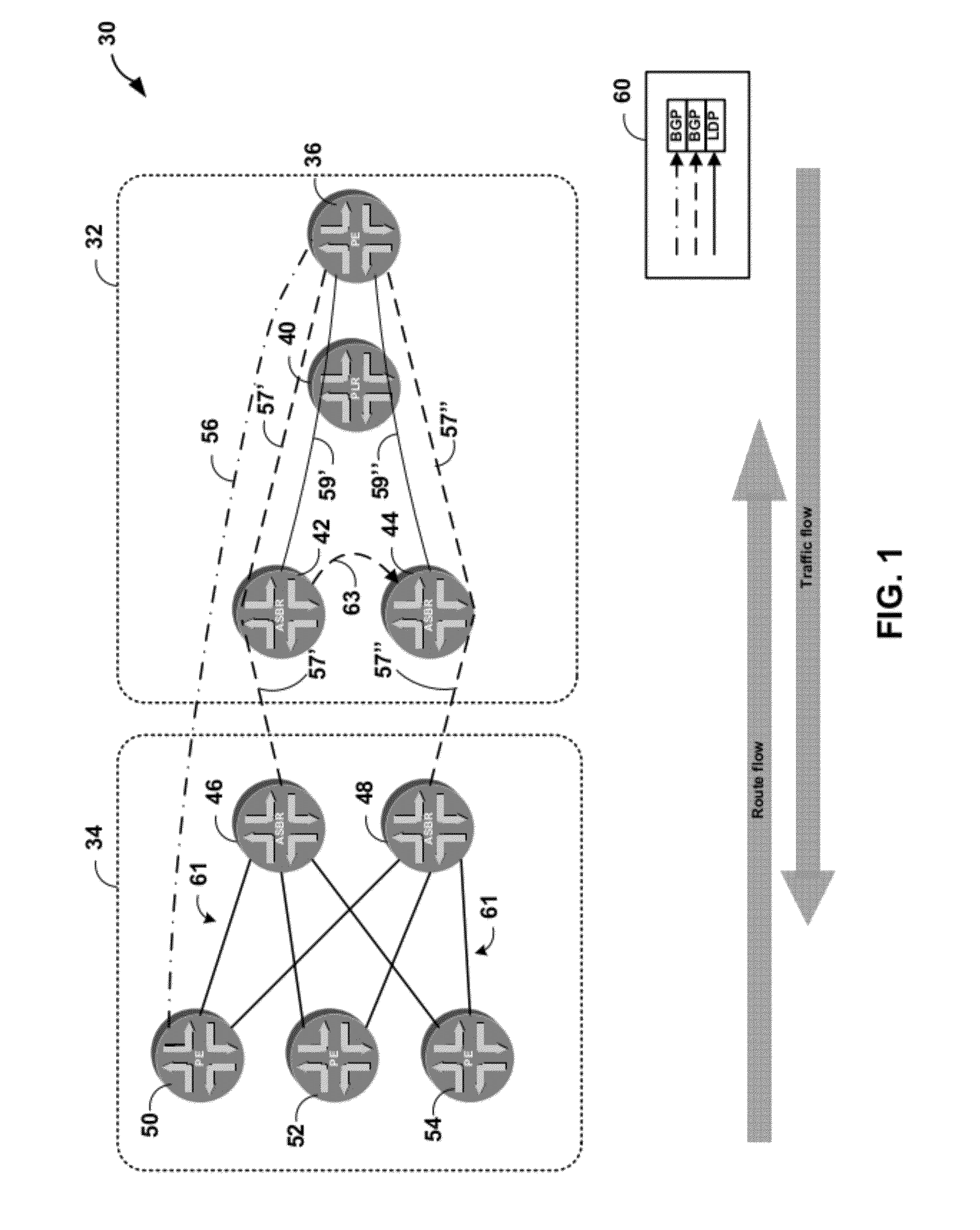
[0024]FIG. 1 is a block diagram illustrating example network 30 that provides protection for an egress router of a label switched path (LSP). In the example of FIG. 1, network 30 includes autonomous system (AS) 32 and AS 34, which are independent systems. In general, an autonomous system is an individual collection of network elements, such as routers, switches, links, or other network devices, maintained by, for example, an Internet service provider or other entity. Routers at the edge of an autonomous system are generally referred to as provider edge (PE) routers. AS 32, for example, includes router 36 that is a provider edge router, and AS 34 includes PE routers 50, 52, and 54. In the example of FIG. 1, label distribution messages (e.g., signaling messages for a label distribution protocol such as LDP or RSVP) for forming an LSP are propagated left-to-right, while data to be transported along the LSP are propagated right-to-left.

[0025]Different autonomous systems may implement di...


PUM


Abstract

This disclosure describes techniques for protecting an endpoint of a label switched path. In one embodiment, a system includes an ingress router, a primary egress router, backup router, and a point of local repair (PLR) router. The ingress router, the PLR router, and the first egress router form a first label switched path. The backup router provides protection for the primary egress router such that the backup router provides routing services for the first egress router when the first egress router is not available. The primary egress router and the backup router share an anycast IP address. The backup router advertises a route to reach the primary egress router, but upon receiving a packet intended for the primary egress router, the backup router identifies the destination of the packet and forwards the packet to the destination instead of the primary egress router along a different route.

Description

[0001]This application claims the benefit of U.S. Provisional Application No. 61 / 122,126, filed Dec. 12, 2008, the entire content of which is incorporated herein by reference.TECHNICAL FIELD[0002]This disclosure relates to computer networks, and more particularly to routing packets within a computer network.BACKGROUND[0003]A computer network is a collection of interconnected computing devices that exchange data and share resources. In a packet-based network, such as the Internet, the computing devices communicate data by dividing the data into small blocks called packets. The packets are individually routed across the network from a source device to a destination device. The destination device extracts the data from the packets and assembles the data into its original form. Dividing the data into packets enables the source device to resend only those individual packets that may be lost during transmission.[0004]Routing devices within a network, often referred to as routers, maintain...

Claims


Application Information

Patent Timeline
Patent Type & Authority Patents(United States)
IPC IPC(8): G06F11/00
CPCG06F11/2005H04L45/507
Inventor GREDLER, HANNESSCUDDER, JOHN GALENSHETH, NISCHALREKHTER, YAKOV
Owner JUMIPER NETWORKS INC
Why Eureka
Try Eureka