Ignition device of internal combustion engine and electrode structure of the ignition device

a technology of ignition device and internal combustion engine, which is applied in the direction of spark plugs, basic electric elements, electric devices, etc., can solve the problems of deterioration in stability of igniting fuel-air mixture, inability to improve combustion efficiency and combustion speed of ignition of fuel-air mixture, and deterioration of stability of discharge, so as to improve the durability of the first electrode and achieve stable generating discharge the effect of spreading

Inactive Publication Date: 2012-09-11
NGK INSULATORS LTD
View PDF12 Cites 17 Cited by
  • Summary
  • Abstract
  • Description
  • Claims
  • Application Information

AI Technical Summary

Benefits of technology

[0010]According to a first aspect of the present invention, an electrode structure of an ignition device for igniting a fuel-air mixture filling a combustion space of an internal combustion engine, includes a first electrode that is made of a conductor and has a bar shape, a second electrode made of a conductor, an auxiliary electrode made of a conductor, a first dielectric barrier that is made of a dielectric body and partially coats a surface of the first electrode, and a second dielectric barrier that is made of a dielectric body and entirely or partially coats a surface of the auxiliary electrode, wherein the surface of the first electrode includes a first exposed surface exposed in the combustion space, and a first coated surface coated with the first dielectric barrier, a surface of the second electrode includes a second exposed surface exposed in the combustion space, and the surface of the auxiliary electrode includes a second coated surface coated with the second dielectric barrier, the first exposed surface is opposed to the second exposed surface with the combustion space therebetween, the first coated surface is opposed to the second coated surface with the first dielectric barrier, the combustion space, and the second dielectric barrier therebetween, and a first distance from the first coated surface to the second coated surface via the first dielectric barrier, the combustion space, and the second dielectric barrier is shorter than a second distance from the first exposed surface to the second exposed surface via the combustion space.
[0021]According to the first to ninth aspects of the present invention, after a pre discharge is generated between the first coated surface and the second coated surface, a main discharge is generated between the first exposed surface and the second exposed surface, and thus the main discharge is stabilized, thereby stably generating discharge spreading widely and three-dimensionally.
[0026]According to the sixth aspect of the present invention, an electric field concentrates on an apex and thus the main discharge is easily generated.
[0028]According to the eighth aspect of the present invention, when the first electrode is worn away, a curvature of the first exposed surface becomes small and the main discharge is easily generated. As a result, disturbance of the generation of the main discharge is hardly made by the wear of the first electrode, thereby improving durability of the first electrode.
[0029]According to the tenth and eleventh aspects of the present invention, after the pre discharge is generated between the first coated surface and the second coated surface, the main discharge is generated between the exposed surface and the inner wall, and the main discharge becomes stable, thereby stably generating discharge spreading widely and three-dimensionally.

Problems solved by technology

Further, depending on compositions and pressures of the fuel-air mixtures, discharge is generated at unintended timing and the spark plugs may be damaged by arc discharge, thereby causing a problem that the stability of the discharge is deteriorated.
Since the compositions and pressures of the fuel-air mixtures are not constant, the deterioration in the stability of the discharge causes deterioration in stability of igniting the fuel-air mixtures.
However, when the gaps between the anodes and the cathodes are not widened, a discharge that spread widely and three-dimensionally is not generated, thereby causing another problem such that combustion efficiency and a combustion speed of the ignition of the fuel-air mixtures are not improved.

Method used


Image

  • Ignition device of internal combustion engine and electrode structure of the ignition device
  • Ignition device of internal combustion engine and electrode structure of the ignition device
  • Ignition device of internal combustion engine and electrode structure of the ignition device

Examples


first embodiment

[0058]{First Embodiment}

[0059]A first embodiment relates to an electrode structure of an ignition device for igniting a fuel-air mixture filling a combustion space (combustion chamber) of an internal combustion engine.

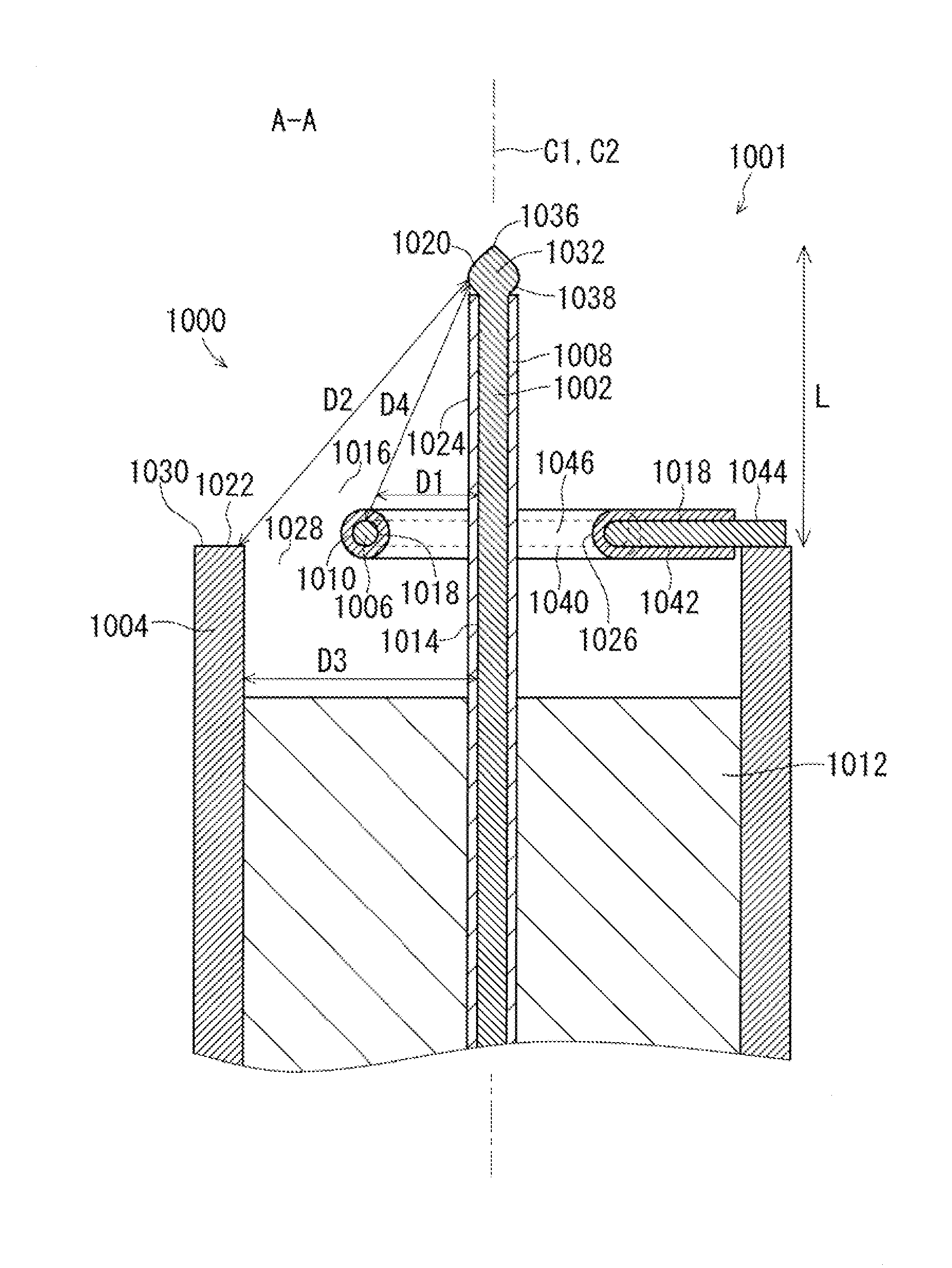
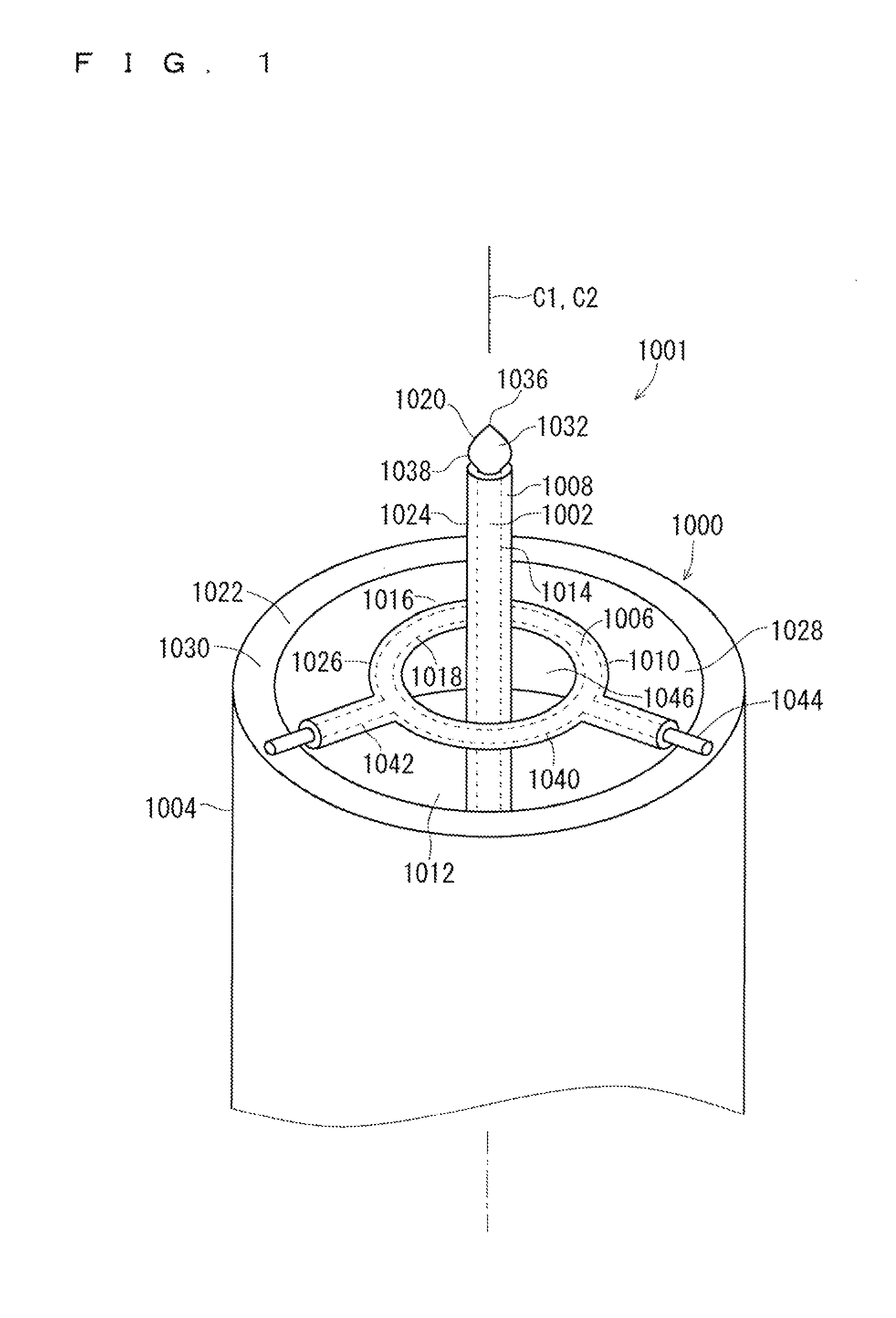
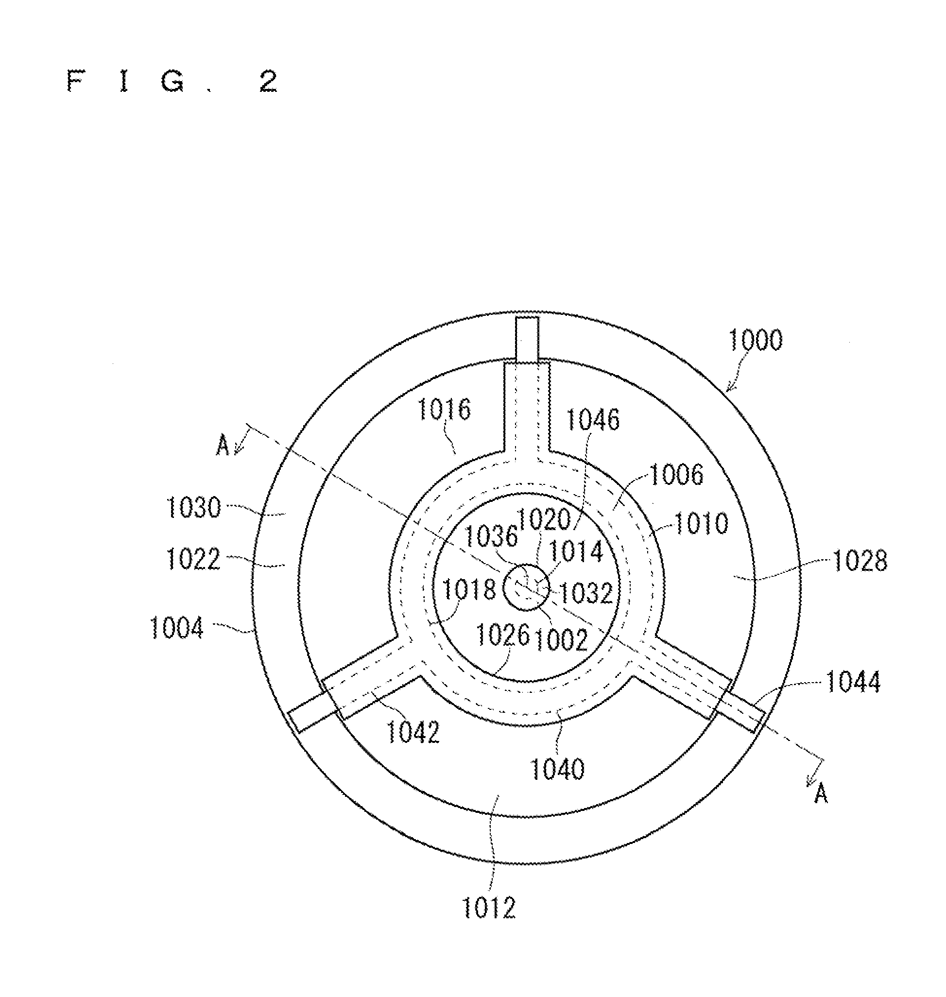
[0060]FIG. 1, FIG. 2, and FIG. 3 are schematic diagrams illustrating an electrode structure 1000 according to the first embodiment. FIG. 1 is a perspective view, FIG. 2 is a top view, and FIG. 3 is a cross-sectional view taken along line A-A in FIG. 2.

[0061]As shown in FIG. 1, FIG. 2, and FIG. 3, the electrode structure 1000 has an anode 1002, a cathode 1004, an auxiliary electrode 1006, an anode coating 1008, an auxiliary electrode coating 1010, and an anode supporting body 1012. The electrode structure 1000 is mounted to a combustion bomb formed with a combustion space 1016 similarly to a conventional spark plug, and a front end 1001 of the electrode structure 1000 is exposed in the combustion space 1016. The anode 1002 may be used as the cathode, and the cathode 100...

second embodiment

[0119]{Second Embodiment}

[0120]A second embodiment relates to an electrode structure of the ignition device for igniting the fuel-air mixture filling the combustion space of the internal combustion engine.

[0121]FIG. 18 and FIG. 19 are schematic diagrams illustrating an electrode structure 2000 according to the second embodiment. FIG. 18 is a perspective view, and FIG. 19 is a cross-sectional view.

[0122]As show in FIG. 18 and FIG. 19, the electrode structure 2000 includes an anode 2002, a cathode 2004, an auxiliary electrode 2006, an anode coating 2008, and an anode supporting body 2012. The anode 2002 may be used as the cathode, and the cathode 2004 may be used as the anode.

[0123](Common Point and Different Point with Respect to Electrode Structure 1000 According to First Embodiment)

[0124]A first difference between the electrode structure 1000 according to the first preferred embodiment and the electrode structure 2000 according to the second preferred embodiment is that the auxilia...

third embodiment

[0127]{Third Embodiment}

[0128](Outline)

[0129]A third embodiment relates to the electrode structure of the ignition device for igniting the fuel-air mixture filling the combustion space of the internal combustion engine.

[0130]FIG. 20, FIG. 21, and FIG. 22 are schematic diagrams illustrating a combustion bomb 3004 and an electrode structure 3000 according to the third embodiment. FIG. 20 is a perspective view, FIG. 21 is a transverse cross-sectional view, and FIG. 22 is a vertical cross-sectional view taken along line B-B of FIG. 21.

[0131]As shown in FIG. 20, FIG. 21, and FIG. 22, the electrode structure 3000 has an anode 3002, an auxiliary electrode 3006, an anode coating 3008, and an auxiliary electrode coating 3010. Main parts of the electrode structure 3000 are housed in a combustion space 3016 formed in the combustion bomb 3004 made of a conductor. The combustion bomb 3004 is used instead of the cathode. The anode 3002 may be used as the cathode, and the combustion bomb 3004 may ...


PUM

PropertyMeasurementUnit
dielectricaaaaaaaaaa
dielectric barrieraaaaaaaaaa
distanceaaaaaaaaaa

Abstract

An ignition device having an electrode structure including an anode, a cathode, an auxiliary electrode, an anode coating, an auxiliary electrode coating, and an anode supporting body. A coated surface of the anode is opposed to a coated surface of the auxiliary electrode with the anode coating, a combustion space, and the auxiliary electrode coating therebetween. An exposed surface of the anode is opposed to an exposed surface of the cathode with the combustion space therebetween. A distance D1 from the coated surface of the anode to the coated surface of the auxiliary electrode via the anode coating, the combustion space, and the auxiliary electrode coating is shorter than a distance D2 from the exposed surface of the anode to the exposed surface of the cathode via the combustion space (D1<D2). A combustion bomb may be used as the cathode.

Description

FIELD OF THE INVENTION[0001]The present invention relates to an ignition device of an internal combustion engine and an electrode structure of the ignition device.BACKGROUND OF THE INVENTION[0002]Spark plugs for generating discharge in gaps between anodes and cathodes are widely used in order to ignite fuel-air mixtures filling combustion spaces of internal combustion engines such as automobile engines.[0003]In the spark plugs, when the gaps between the anodes and cathodes are widened, discharge is not generated if voltages to be applied between the anodes and the cathodes are not heightened. Further, depending on compositions and pressures of the fuel-air mixtures, discharge is generated at unintended timing and the spark plugs may be damaged by arc discharge, thereby causing a problem that the stability of the discharge is deteriorated. Since the compositions and pressures of the fuel-air mixtures are not constant, the deterioration in the stability of the discharge causes deterio...

Claims


Application Information

Patent Timeline
Patent Type & Authority Patents(United States)
IPC IPC(8): H01T13/20H01T13/34
CPCH01T13/467H01T13/52
Inventor SHIMODA, KENJIRO
Owner NGK INSULATORS LTD
Why Eureka
Try Eureka