
Ballast-filled pipeline weight

a technology of ballast and pipeline, which is applied in the direction of pipe supports, pipe laying and repair, containers, etc., can solve the problems of inconvenient and adaptable prior art bag-type weights for ballasting large-diameter pipes, and the difficulty of ballast for larger-diameter pipelines

Active Publication Date: 2012-09-11
KEYMAY IND
View PDF22 Cites 11 Cited by
  • Summary
  • Abstract
  • Description
  • Claims
  • Application Information

AI Technical Summary

Benefits of technology

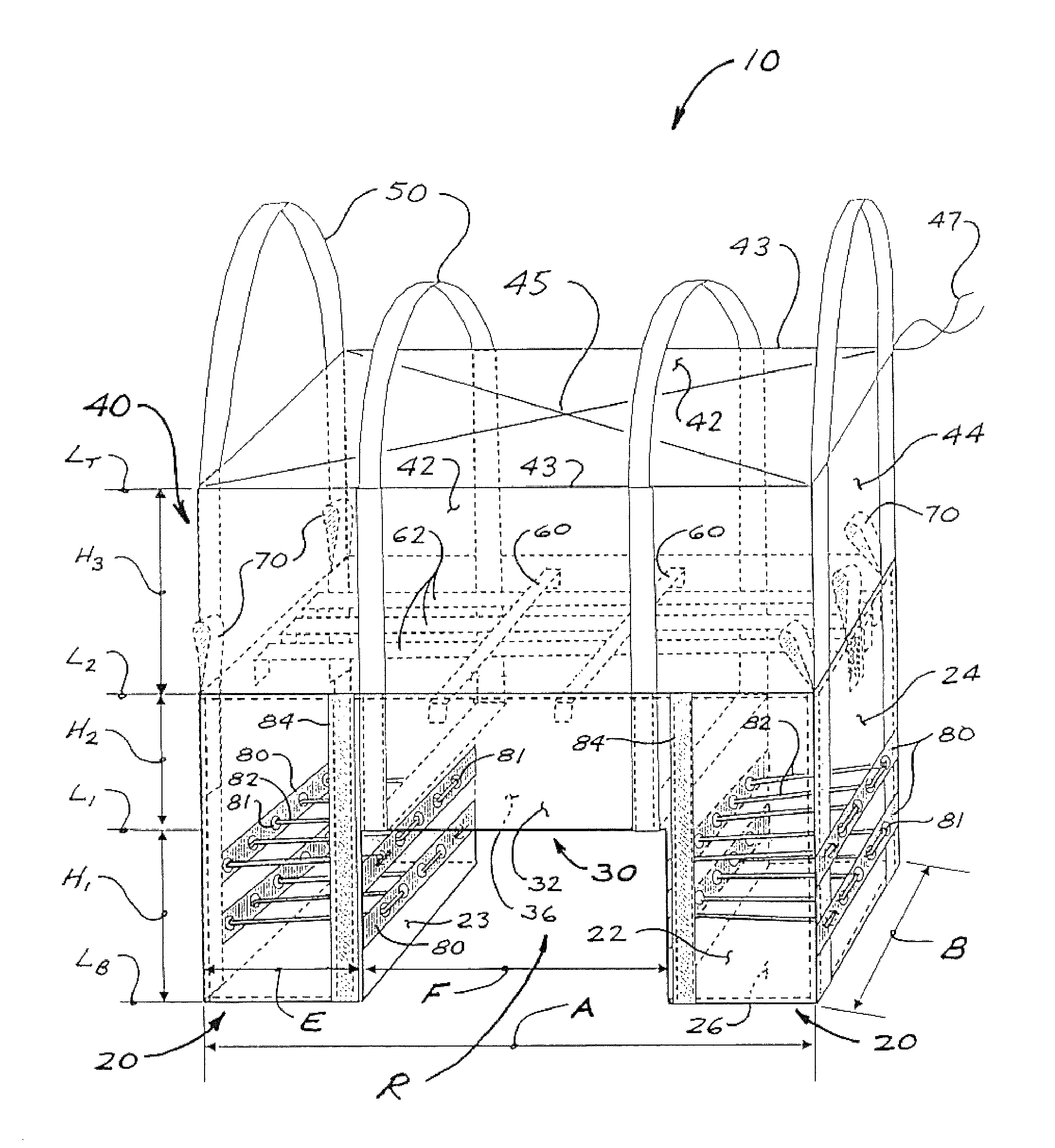
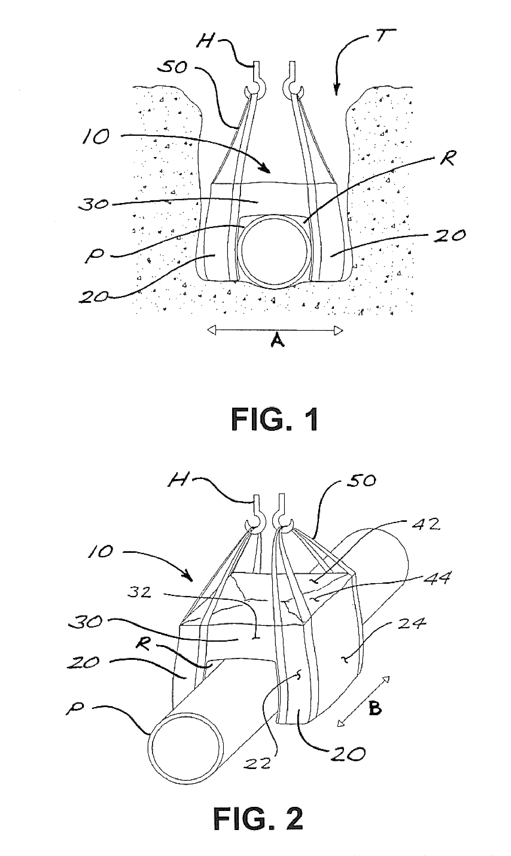
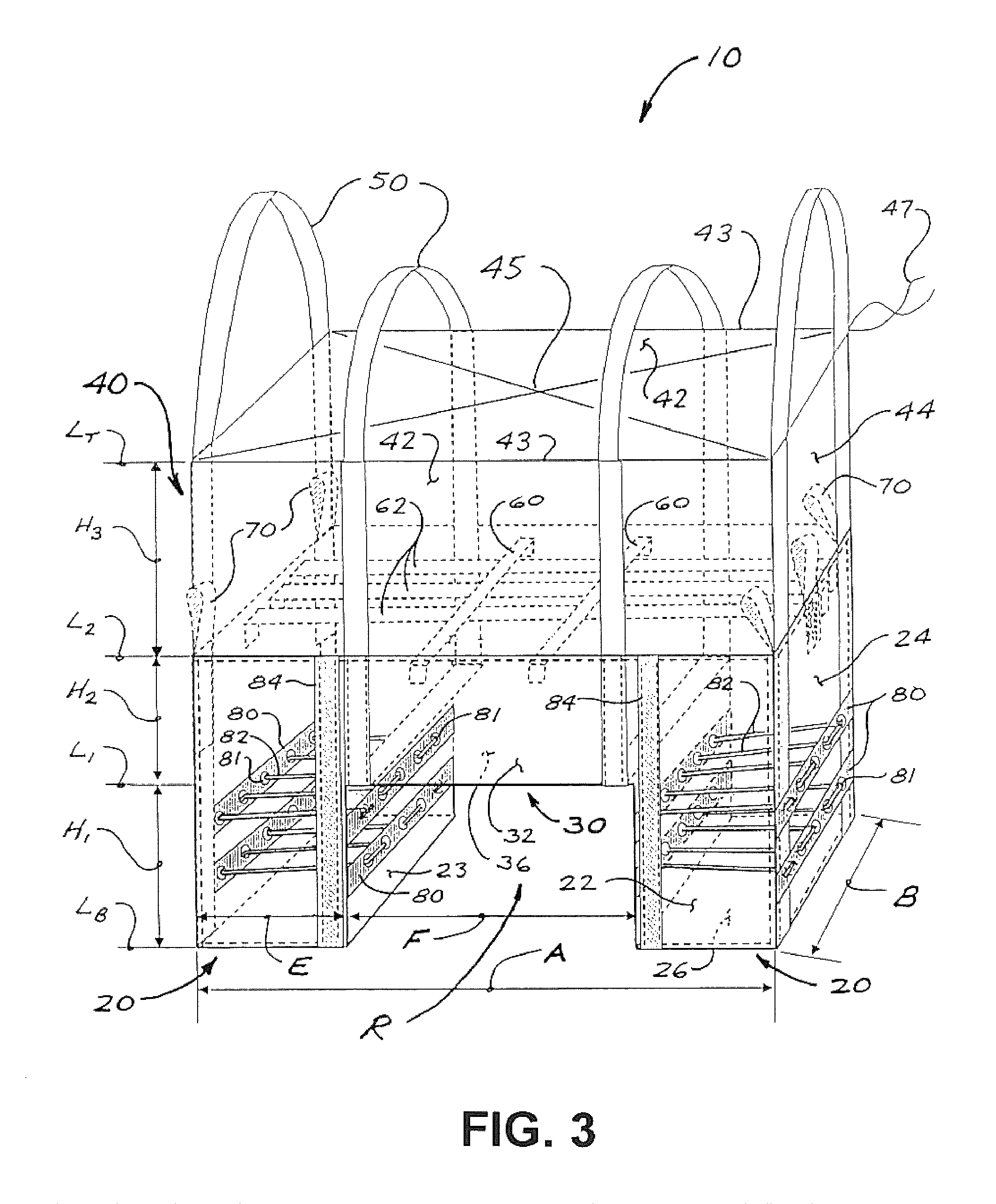
[0011]The present invention provides a flexible bag-type pipeline weight configured to straddle a pipeline, with internal tic means for preventing excessive bulging of the weight during or after being filled with ballasting material, thus facilitating installation in comparatively narrow pipeline trenches. Built-in loading loops facilitate filling the weight with gravel or other ballasting material, without need for special loading hoppers or other complex equipment. The pipeline weight of the present invention is formed with a pair of leg sections on either side of a central, pipeline-receiving recess. Once filled with ballast, the legs remain separated, thus facilitating installation on a pipeline. The filled pipeline weight is also freestanding and stable for purposes of transport and storage prior to installation. Hoisting slings may be used to facilitate lifting and manipulation of loaded pipeline weights without the need for spreader bars.

Problems solved by technology

The problem of providing ballast for larger diameter pipelines (e.g., 16-inch plus) has particular challenges.
Because of their inherent configurations, prior art bag-type weights are not suitable or readily adaptable for ballasting large-diameter pipe.
For example, weights such as those taught by Jewell are not readily scalable to accommodate the much greater mass of ballast required for large-diameter pipelines.
The Connors design, if scaled up to hold greatly increased amounts of ballast, will be difficult to fill, handle, and install, particularly where it is desired or necessary to install a pipeline in a trench with minimum possible side clearances.

Method used


Image

  • Ballast-filled pipeline weight
  • Ballast-filled pipeline weight
  • Ballast-filled pipeline weight

Examples


Embodiment Construction

[0018]FIGS. 1 and 2 illustrate a pipeline weight 10 in accordance with one embodiment of the present invention, being positioned over a pipeline P in a trench T. Pipeline weight 10 has a nominal overall width A and a nominal length B (parallel to pipeline P). Weight 10 preferably has a plurality of hoisting slings 50 which in FIGS. 1 and 2 are shown being supported by hoisting means conceptually indicated by lifting hooks H. Weight 10 is fashioned from a suitable flexible fabric or similar material, which in preferred embodiments will be a geotextile.

[0019]Tables 1 and 2 provide data relating to weights and preferred materials for non-limiting examples of embodiments of weight 10 for selected combinations of pipe size, weight width A, and weight length B.

[0020]

TABLE 1Bag Dimensions on PipeWeightsPipe SizeABlbkg16″36″84″2,5001,13420″45″96″5,0002,26824″54″96″5,0002,26830″67″96″7,0003,17536″81″96″9,0004,08042″94″96″12,5005,44048″108″ 96″12,5005,440

[0021]

TABLE 2Bag Material DataGeotexti...


PUM


Abstract

A flexible bag-type pipeline weight, configured to straddle a pipeline, has internal tie means to prevent excessive bulging of the weight after being filled with ballasting material, thus facilitating installation in narrow trenches. Built-in loading loops facilitate filling the weight with ballasting material without need for special loading equipment. The bag-type pipeline weight is formed with a pair of leg sections on either side of a central, pipeline-receiving recess. Once filled with ballast, the legs remain separated, thus facilitating installation on a pipeline. The filled pipeline weight is also freestanding and stable for purposes of transport and storage prior to installation. Hoisting slings facilitate lifting and manipulation of loaded pipeline weights without the need for spreader bars.

Description

CROSS-REFERENCE TO RELATED APPLICATIONS[0001]This application claims the benefit, pursuant to 35 U.S.C. 119(c), of Provisional Application No. 61 / 148,299, filed on Jan. 29, 2009, and said provisional application is incorporated herein by reference in its entirety for continuity of disclosure.FIELD OF THE INVENTION[0002]The present invention relates in general to means for anchoring or preventing flotation of pipelines, such as oil and gas pipelines. In particular, the invention relates to bag-type weights for large diameter pipelines.BACKGROUND OF THE INVENTION[0003]Weights of various types are commonly used to anchor pipelines, particularly for pipelines running through water bodies, marshes, sloughs, or other moisture-laden zones in which pipelines might be upwardly displaced due to buoyancy forces. Bag-type pipeline weights are typically made from a flexible and durable fabric or similar material, with pockets or compartments that can be filled with ballast material (such as grav...

Claims


Application Information

Patent Timeline
Patent Type & Authority Patents(United States)
IPC IPC(8): F16L1/06B65D33/14
CPCF16L1/06F16L1/24
Inventor GUNN, DONALD O.REID, LYLE CONNLEY
Owner KEYMAY IND
Learn More