Coaxial cable assembly connection structure and method

Inactive Publication Date: 2012-09-11
DISTINCT INTUITIVE DESIGNS
View PDF31 Cites 49 Cited by
  • Summary
  • Abstract
  • Description
  • Claims
  • Application Information

AI Technical Summary

Benefits of technology

[0018]It is another object of the invention to provide enhanced connector features

Problems solved by technology

Such a configuration suffers from the disadvantage that electrical contact is dependent entirely on the pressure exerted by the heat-shrinkable member due to the non-deformability of the flange.
Additionally, this structure does not provide for a high pull strength cable assembly.
Nonetheless, there is no teaching of how the braid is used to interconnect coaxial cable with a non-deformable shell or solder impregnation.
All the above

Method used


Image

  • Coaxial cable assembly connection structure and method
  • Coaxial cable assembly connection structure and method
  • Coaxial cable assembly connection structure and method

Examples


Example

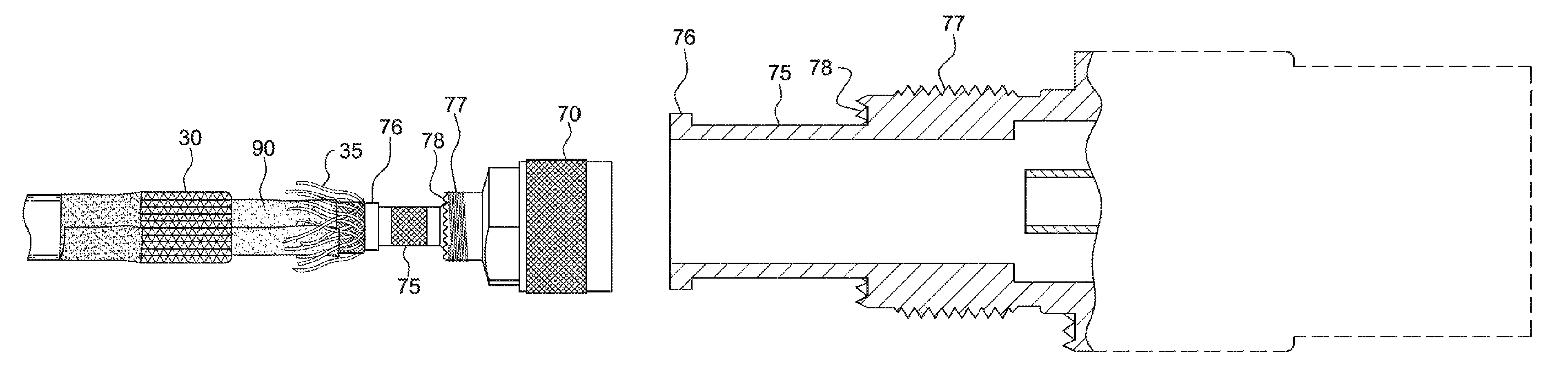
[0047]Generally speaking, the present invention features a novel connector back end, and a method of terminating a coax cable to a connector, that facilitates the manufacturing of a field repairable, high pull strength, electrically superior cable assembly. The method includes the steps of covering a portion of the cable with an unfolded layer of braiding and employing a band to the braiding and connector. Previous methods of coax terminations were limited in strength of connector junction due to styling that placed the bulk of bending, tension, and compression stresses on the outer jacket insulation, and by compression proximity, the inner layers of the cable. This allowed slippage of the connector under the crimp, overcoming the stiction of the crimped cable, thereby weakening the connector and allowing ingress of unwanted signal attenuation or outright disruption.

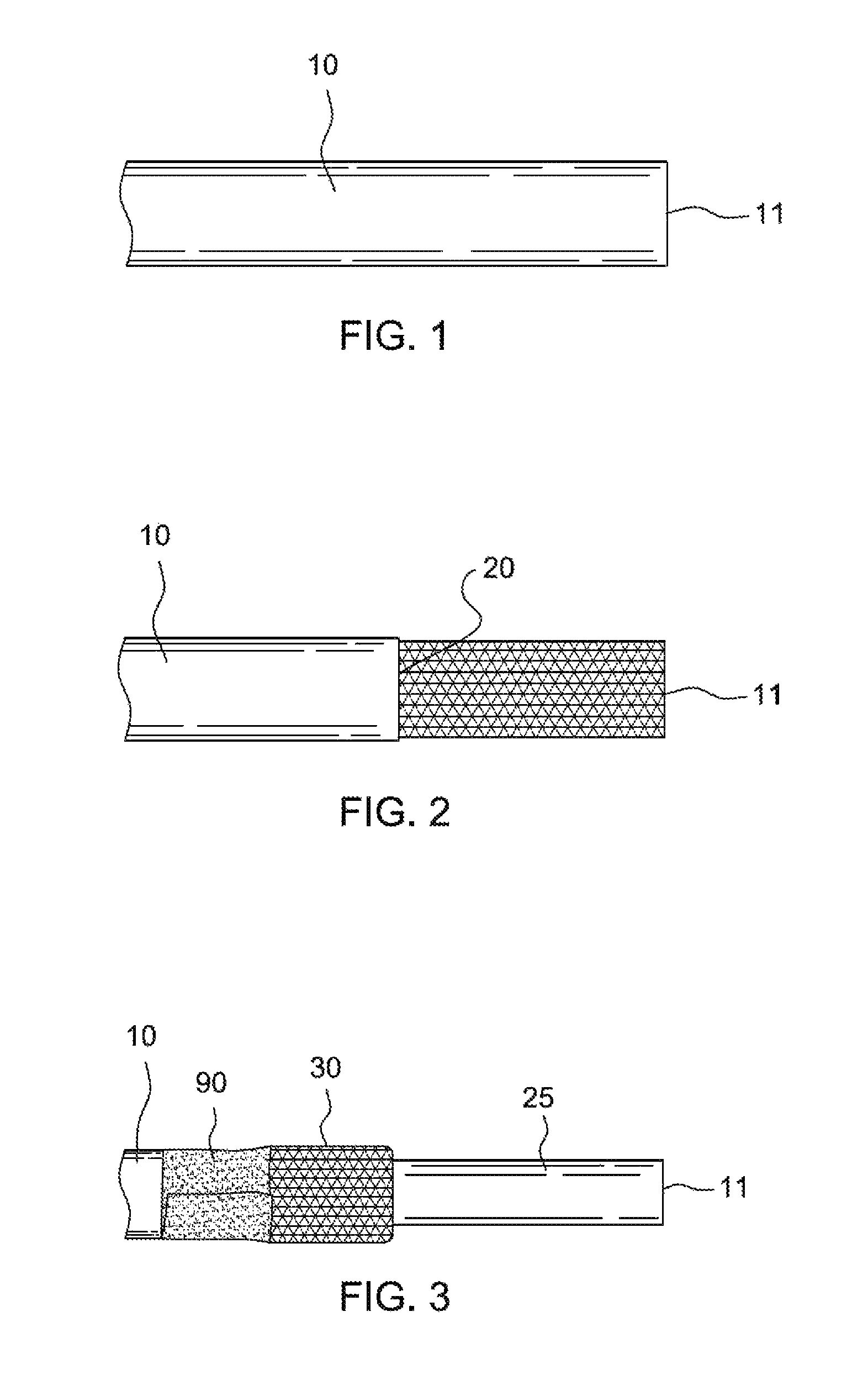
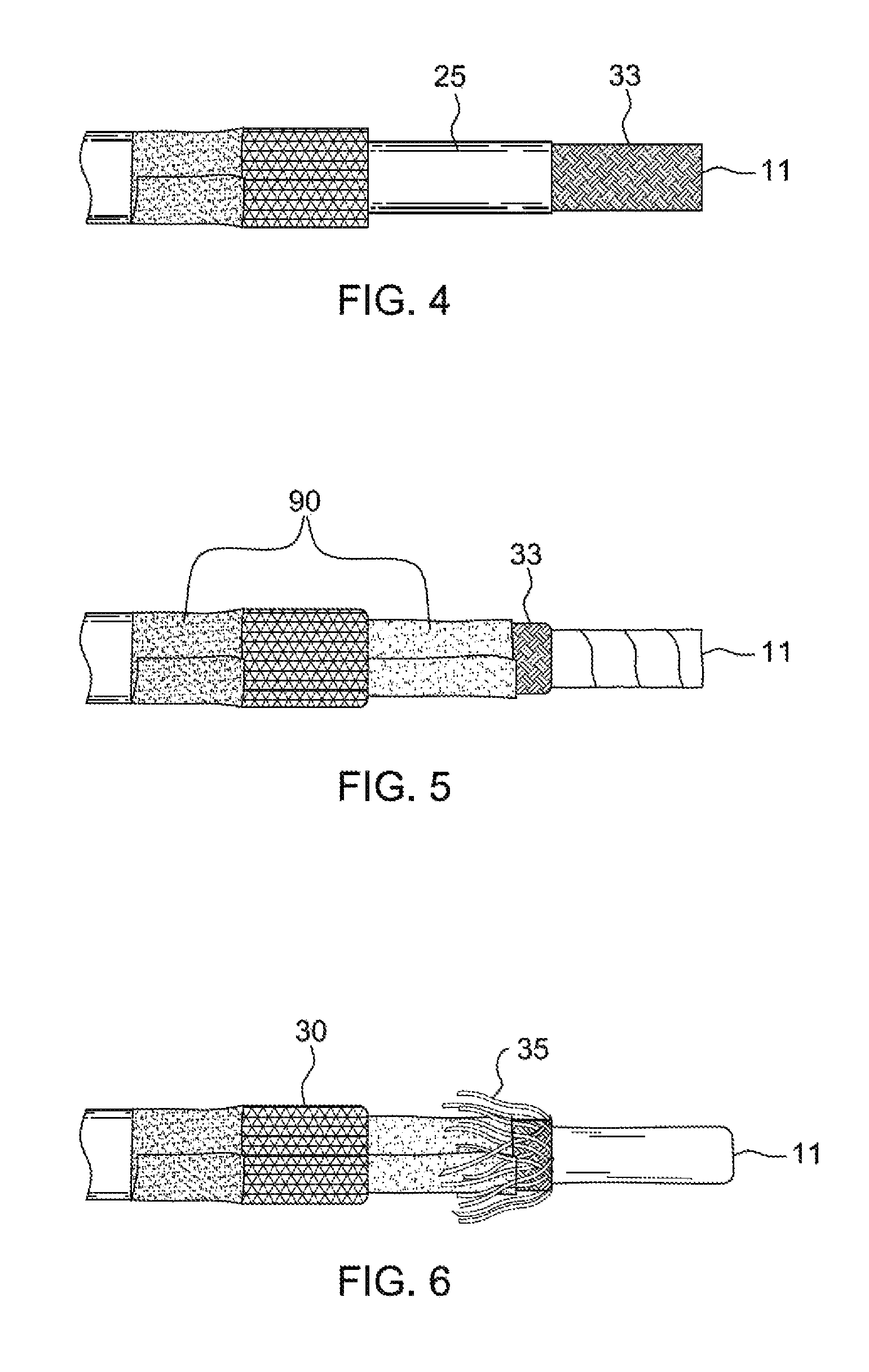
[0048]For ease of understanding described embodiment, like reference numbers are used throughout the figures to callou...


PUM


Abstract

A structure for the back end of repairable connectors, applicable for a variety of RF connectors, that facilitates superior mechanical and electrical characteristics of the resulting coax cable assembly. Also disclosed is a method of attaching one of various repairable connectors to coax cable that is both simple and stronger than existing methods. The outside insulation is removed from the end of the cable and the braiding is folded back out of the way. Depending on the number of layers of braiding, this step may be performed more than once. The dielectric surrounding the center conductor is then trimmed to expose the conductor. In one embodiment, a pin is soldered in-line with the center conductor. The connector is then placed on one end of the prepared cable and the braiding is unfolded. A band is then applied to secure the braiding against the connector, making a strong bond.

Description

FIELD OF THE INVENTION[0001]The invention relates generally to methods and structural features to enable attaching coaxial cable to connectors and, more specifically, to a specialized attachment structure and method that securely attaches a connector to a coaxial cable, and that achieves superior mechanical and electrical characteristics.BACKGROUND OF THE INVENTION[0002]Coaxial (coax) cable is nearly ubiquitous in today's technology-based, information-driven society. It is used in a wide variety of applications, including broadband Internet and cable television, as well as specialty applications, including a wide variety of radio frequency (RF) antennae applications.[0003]Coaxial cable generally includes a central axial conductor element and one or more outer conductor elements wrapped concentrically around the central axial conductor. A low-loss, high dielectric insulation material separates the conductors. In most applications, an outer insulating cover is provided to shield the o...

Claims


Application Information

Patent Timeline
IPC IPC(8): H01R9/05
CPCH01R9/0524H01R4/72H01R2103/00
Inventor KELLY, MARK A.
Owner DISTINCT INTUITIVE DESIGNS
Why Eureka
Try Eureka