

Canulated titanium implant for correcting flat feet in children
a technology of titanium implants and flat feet, which is applied in the field of canulated titanium implants for children's flat feet correction, can solve the problems of long-term (several weeks) mobilization, broken inserted screws, and delayed post-operative recuperation, so as to improve the healing effect, avoid damage to cartilage and improve the healing
- Summary
- Abstract
- Description
- Claims
- Application Information
AI Technical Summary
Benefits of technology
Problems solved by technology
Method used
Image

Examples
Embodiment Construction
[0001]1. Field of the Invention
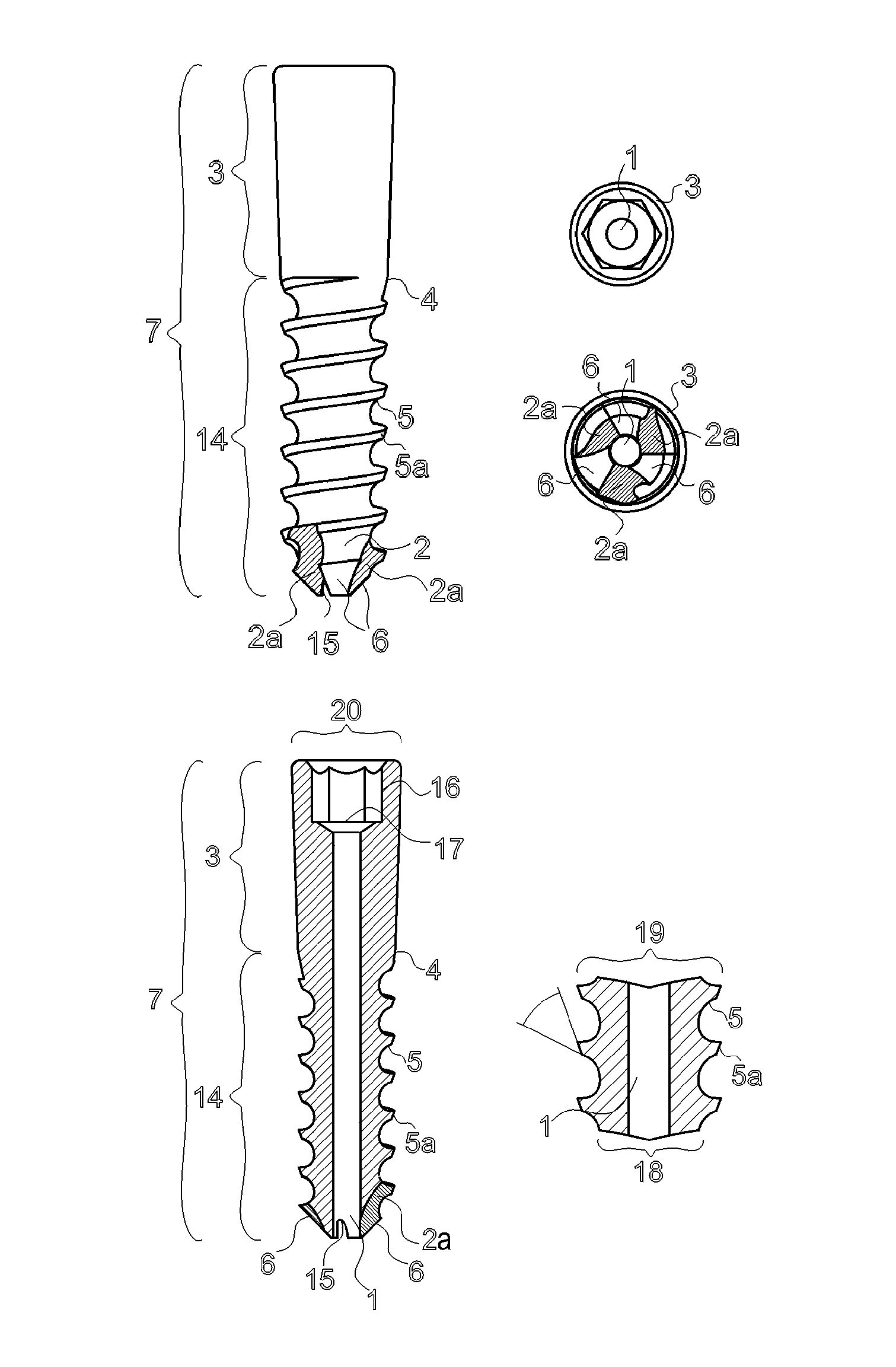
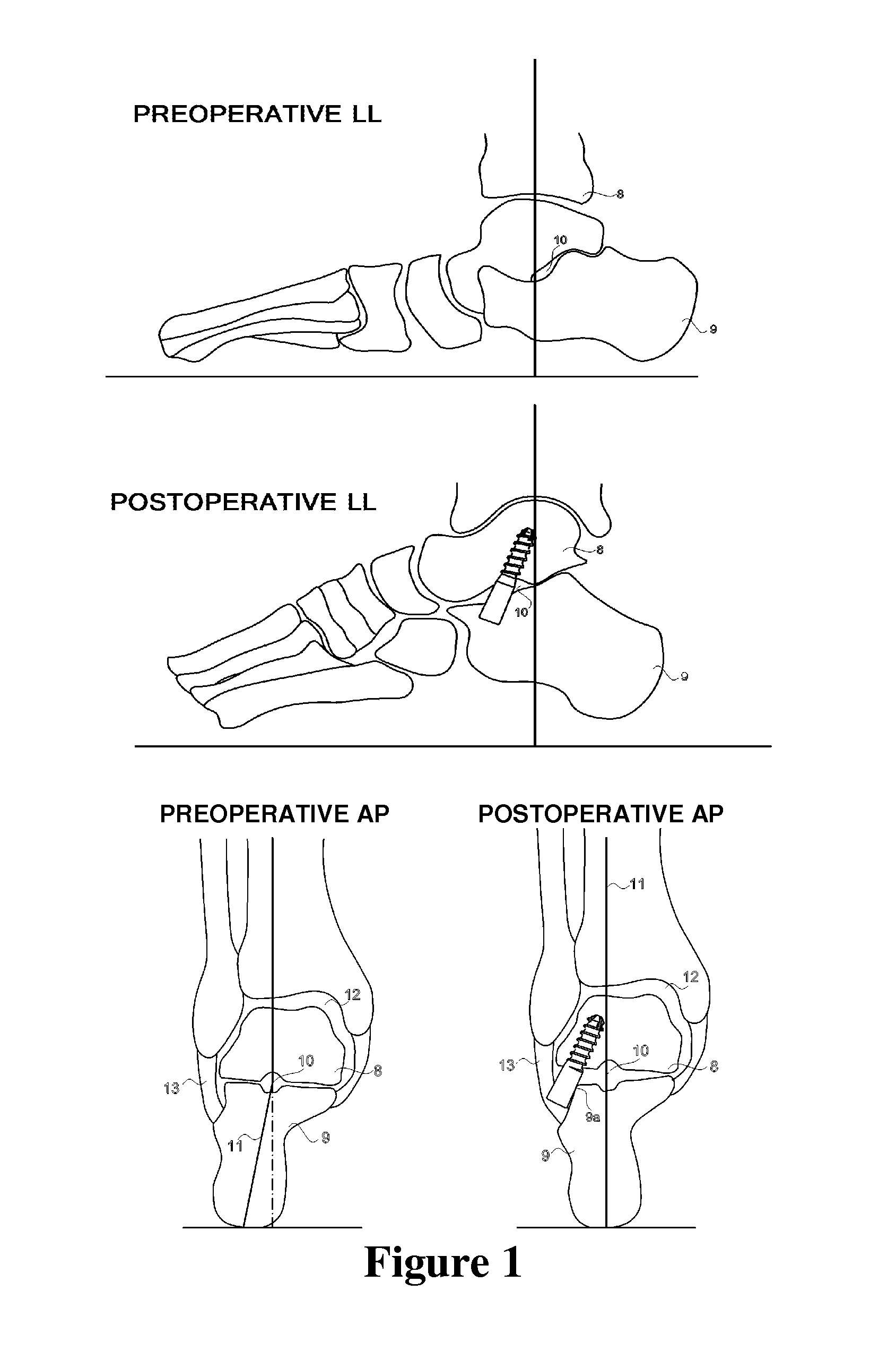
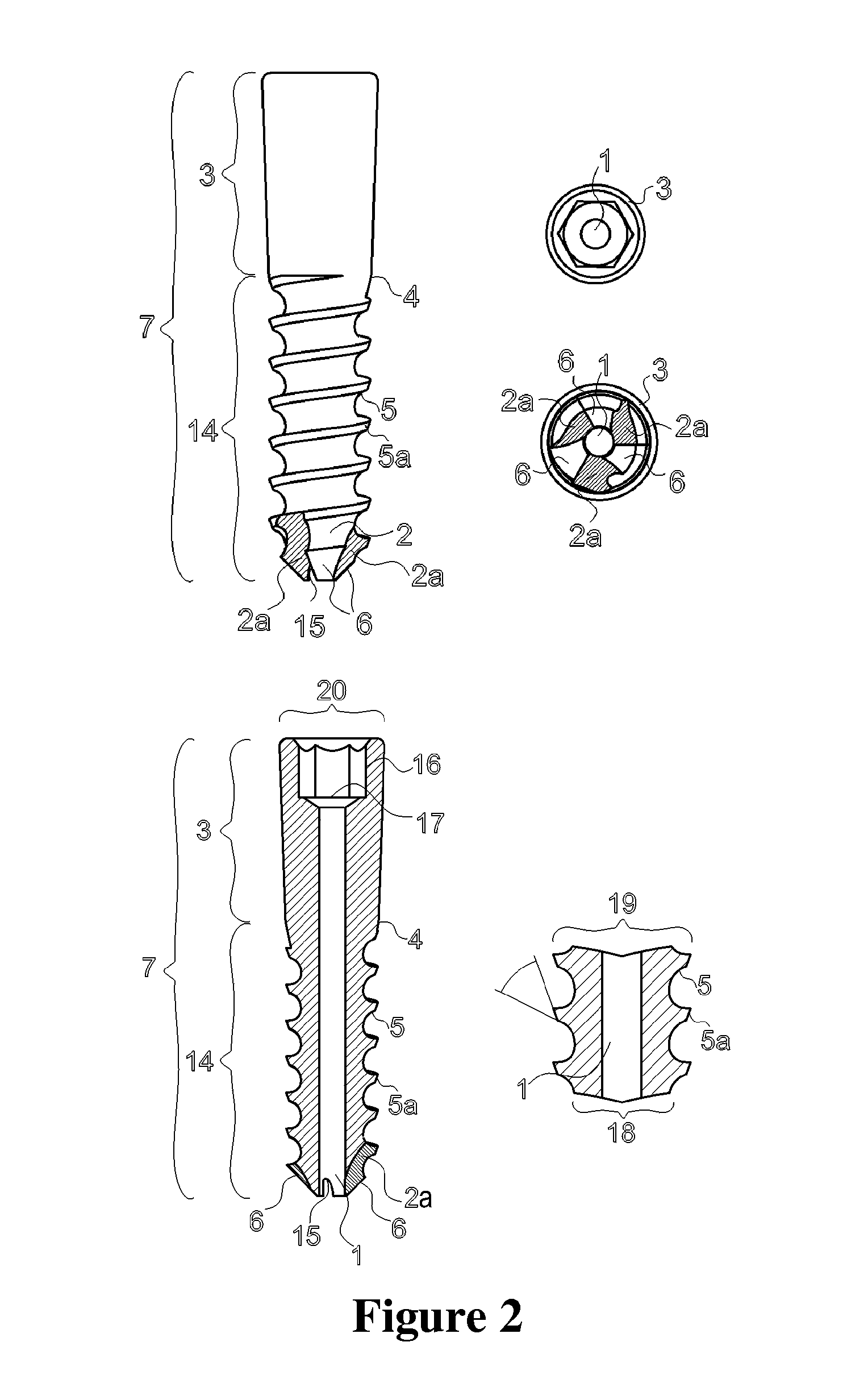
[0002]This invention was designed for the operative correction of extremely flat feet in children with a heel valgus (Pes planovalgus gr III-IV), which inspite of using all existing physical methods of correction and usage of orthrotics by the age of twelve could not correct the axis of the heel and bring the arch of the foot to a permanent satisfying result.
[0003]2. Technical Problem
[0004]There have been many years now that one has tried to solve the problem by different surgical methods, but they have up to now demanded operative opening of tarsal bones (by an incision of 30 mm-50 mm), i.e. by opening the operative area to change the relation of tarsal bones (the foot bones), the surrounding tissue needed to be lesioned.
[0005]The screw could have been directed in the right position and into the right place by opening the surface of the bone. Therefore, the post-operative recuperation took longer, and in many cases a long-term (several weeks) mobiliza...
PUM
 Abstract
Description
Claims
Application Information