Electric heater

a technology for electric heaters and heaters, applied in the field of electric heaters, can solve the problems of oxidation problems, and reducing the life of the heater, and achieve the effect of preventing damage to the heating uni

Active Publication Date: 2012-09-18
LG ELECTRONICS INC
View PDF10 Cites 6 Cited by
  • Summary
  • Abstract
  • Description
  • Claims
  • Application Information

AI Technical Summary

Benefits of technology

[0014]Therefore, it is an object of the present invention to provide an electric heater which can prevent damage to a heating unit.
[0015]It is another object of the present invention to provide an electric heater which can prevent damage to a heating unit by controlling a thermal stress concentration and can enhance the output of the electric heater.
[0016]It is another object of the present invention to provide an electric heater which can prevent damage to a heating unit due to eccentric placement of a cooking utensil.Technical Solution

Problems solved by technology

The related art electric heater, i.e., the heater using the heating wires, may have a problem of oxidation caused by direct contacting by air when heated as well as a structural problem to support the heating wires.
Accordingly, damage or cracking easily occurs, thus to reduce its life.

Method used


Image

  • Electric heater
  • Electric heater
  • Electric heater

Examples


first embodiment

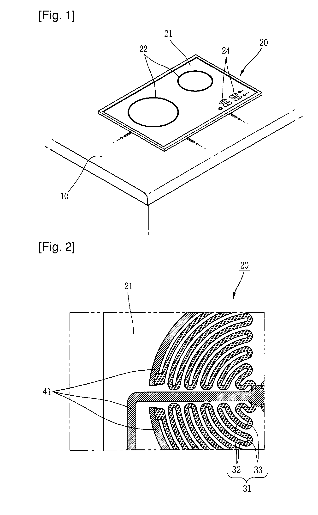
[0041]FIG. 4 is a bottom view showing an electric heater according to the present invention. As shown in the drawing, the electric heater 110 may include a base 111, and a heating unit 121 having a plurality of unit heating elements 123 each implemented as an electrical resistor and spaced from each other on a plate surface of the base 111, and non-heating connection portions 125 conductively connecting the unit heating elements 123 to each other.

[0042]The base 111 is made of a glass member and is formed to have a rectangular plate shape. Cooking utensils, etc. may be placed on a surface of the base 111, i.e., on an upper surface thereof. The unit heating elements 123 and the non-heating connection portions 125 are formed by a method of coating, etc. at another surface of the base 111, i.e., at a lower surface thereof. Here, the base 111 may be formed of a stainless steel, ceramic, aluminum, or the like. The heating unit 121 is disposed to be insulated with the base 111.

[0043]The he...

second embodiment

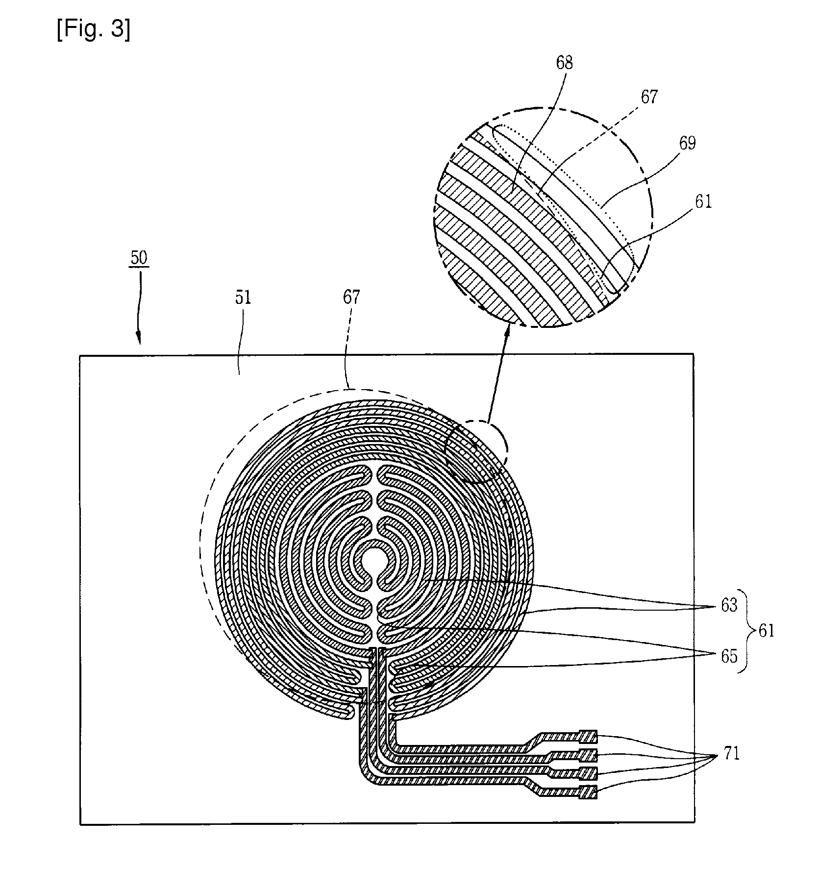
[0047]FIG. 5 is a bottom view showing an electric heater according to the present invention. As shown in the drawing, the electric heater 150 according to the present invention may include a base 151, and a heating unit 161 having a plurality of unit heating elements 165 each implemented as an electrical resistor and spaced from each other on a plate surface of the base 151, and non-heating connection portions 167 conductively connecting the unit heating elements 165 to each other. Here, the base 151 is formed of a glass member, and the non-heating connection portions 167 are formed of a material having a low electrical resistance (e.g., Ag, silver alloy, etc.) so as to have a small heating value, compared to the unit heating elements 165 implemented as electrical resistors.

[0048]The unit heating elements 165 are each formed to have a bar shape having a certain width and length, and are disposed in parallel. This is to prevent a damage due to a temperature gradient in case a cooking...

third embodiment

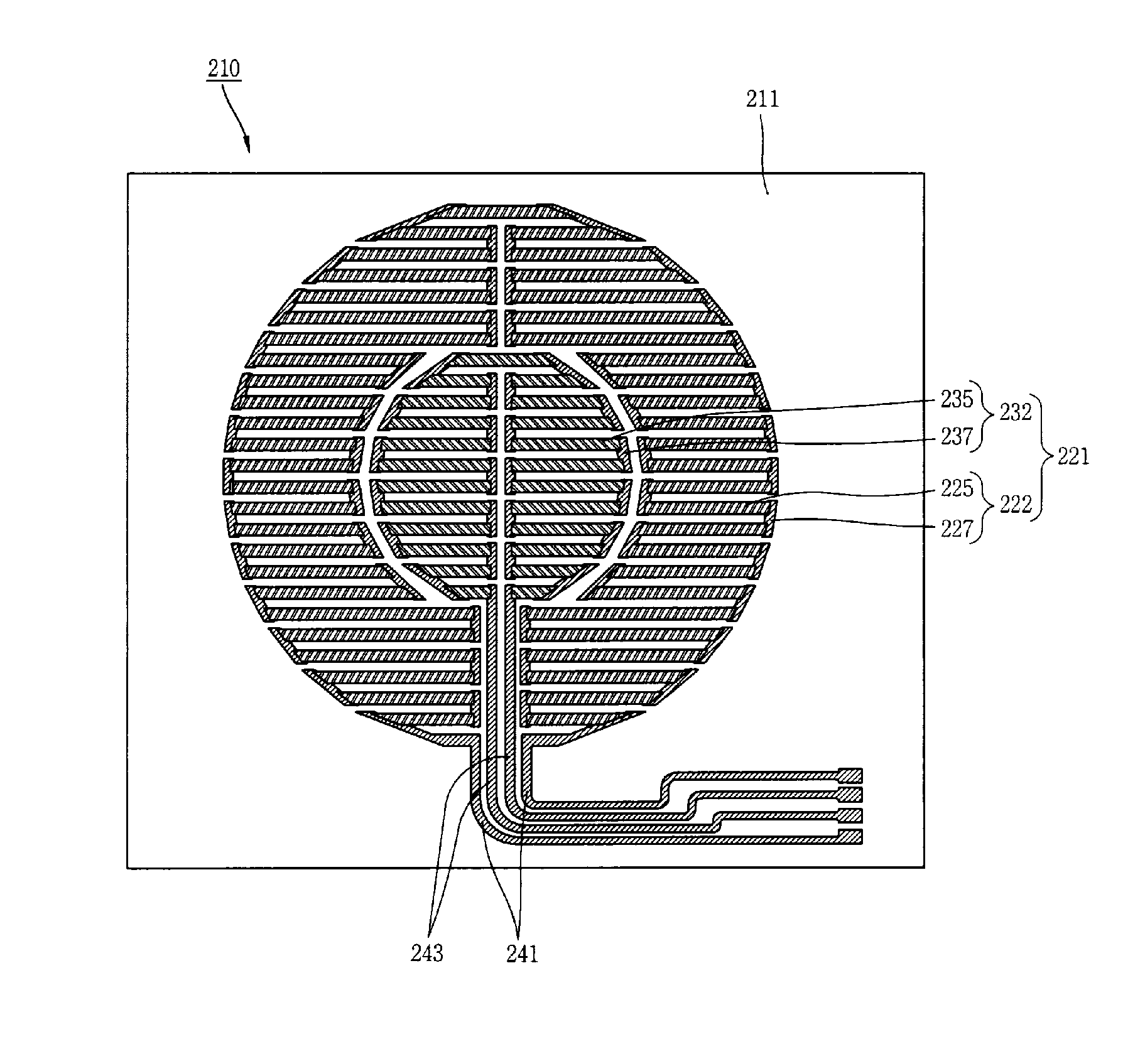
[0051]FIG. 6 is a bottom view showing an electric heater according to the present invention. As shown in the drawing, the electric heater 210 according to the present invention may include a base 211, and a heating unit 221 having a plurality of unit heating elements 225, 235 each implemented as an electrical resistor and spaced from each other on a plate surface of the base 211, and non-heating connection portions 227, 237 conductively connecting the unit heating elements 225, 235 to each other.

[0052]The heating unit 221 is provided with a first heating portion 222 disposed in a radiating direction, and a second heating portion 232 disposed radially inside of the first heating portion 222. The first heating portion 222 and the second heating portion 232 are respectively connected to first power connection portions 241 and second power connection portions 243 for separately being supplied with power.

[0053]Meanwhile, the first heating portion 222 is configured to have a plurality of ...


PUM

PropertyMeasurementUnit
widthaaaaaaaaaa
poweraaaaaaaaaa
shapeaaaaaaaaaa

Abstract

Disclosed is the electric heater including a base, and a heating unit having a plurality of unit heating elements disposed on a plate surface of the base and at least one of heating connection portions configured to heat and conductively connecting the unit heating elements to each other and non-heating connection portions configured not to heat and conductively connecting the unit heating elements to each other, thereby preventing a thermal stress concentration, thus to prevent damage to the heating unit and to enhance its output.

Description

TECHNICAL FIELD[0001]The present invention relates to an electric heater, and more particularly, to an electric heater which is capable of preventing damage to a heating unit.BACKGROUND ART[0002]In general, an electric heater is a heating apparatus which uses heat generated when a current is conducted through a heating element. Electric heaters are typically manufactured by winding or processing heating wires in a specific shape. For instance, the electric heaters may have a structure, in which heating wires wound onto a mica plate or wound in a certain shape are placed inside a quartz tube, or in which a specific material is filled between heating wires and a stainless tube having a certain distance therebetween after the heating wires are placed in the stainless tube.[0003]The related art electric heater, i.e., the heater using the heating wires, may have a problem of oxidation caused by direct contacting by air when heated as well as a structural problem to support the heating wi...

Claims


Application Information

Patent Timeline
Patent Type & Authority Patents(United States)
IPC IPC(8): H05B3/06
CPCH05B3/68H05B3/748
Inventor KIM, JE-HOONKIM, HYOUNG-JUNPARK, BYEONG-WOOK
Owner LG ELECTRONICS INC
Why Eureka
Try Eureka