Sagnac delay-line interferometer for DPSK demodulation

a delay-line interferometer and dpsk technology, applied in the field of telecommunications differential phaseshift keying (dpsk) can solve the problems of difficult and expensive achievement, constructive interference of beams from the two channels, and the effect of greatly reducing the phase requirements of the various optical elements of the interferometer

Inactive Publication Date: 2012-09-18
OPTOPLEX CORP
View PDF9 Cites 19 Cited by
  • Summary
  • Abstract
  • Description
  • Claims
  • Application Information

AI Technical Summary

Benefits of technology

[0011]This invention is based on the idea of implementing a DPSK demodulator using the Sagnac interferometer configuration with a delay line element introduced in one or both of the optical paths of the transmitted and reflected beams. In the Sagnac interferometer, the input beam is split into two beams traveling in opposite directions clockwise and counterclockwise. The two beams are recombined at the beam splitter and interfere to produce two output beams that are 180 degrees out of phase with each other. Because the two beams travel on the same optical path (though in opposite directions), the Sagnac interferometer has all the advantages of a common-path interferometer; that is, both beams experience the same wavefront distortion, phase change on reflection, phase change on transmission, attenuation, etc. Therefore, the interferometer is thermally and mechanically stable and the phase requirements for the various optical elements of the interferometer are greatly reduced.

Problems solved by technology

After the recombination, the beams from the two channels interfere constructively and destructively.
This is difficult and expensive to achieve, especially for an interferometer with a long optical path.

Method used


Image

  • Sagnac delay-line interferometer for DPSK demodulation
  • Sagnac delay-line interferometer for DPSK demodulation
  • Sagnac delay-line interferometer for DPSK demodulation

Examples


Embodiment Construction

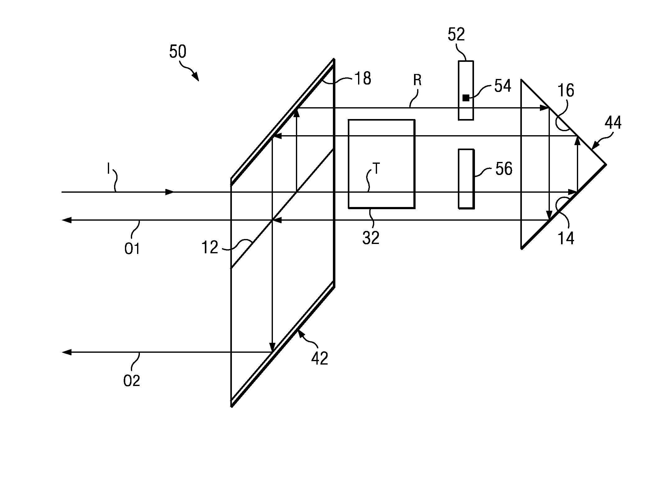
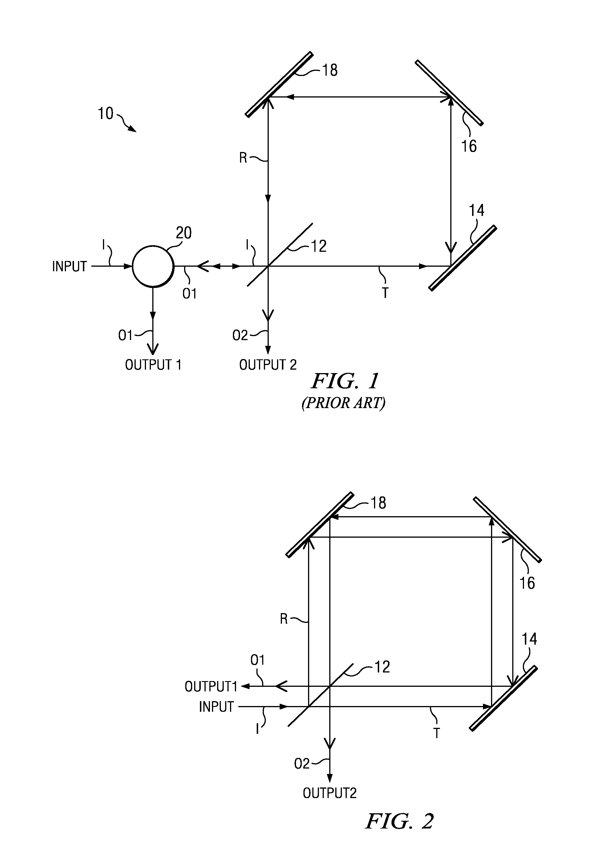
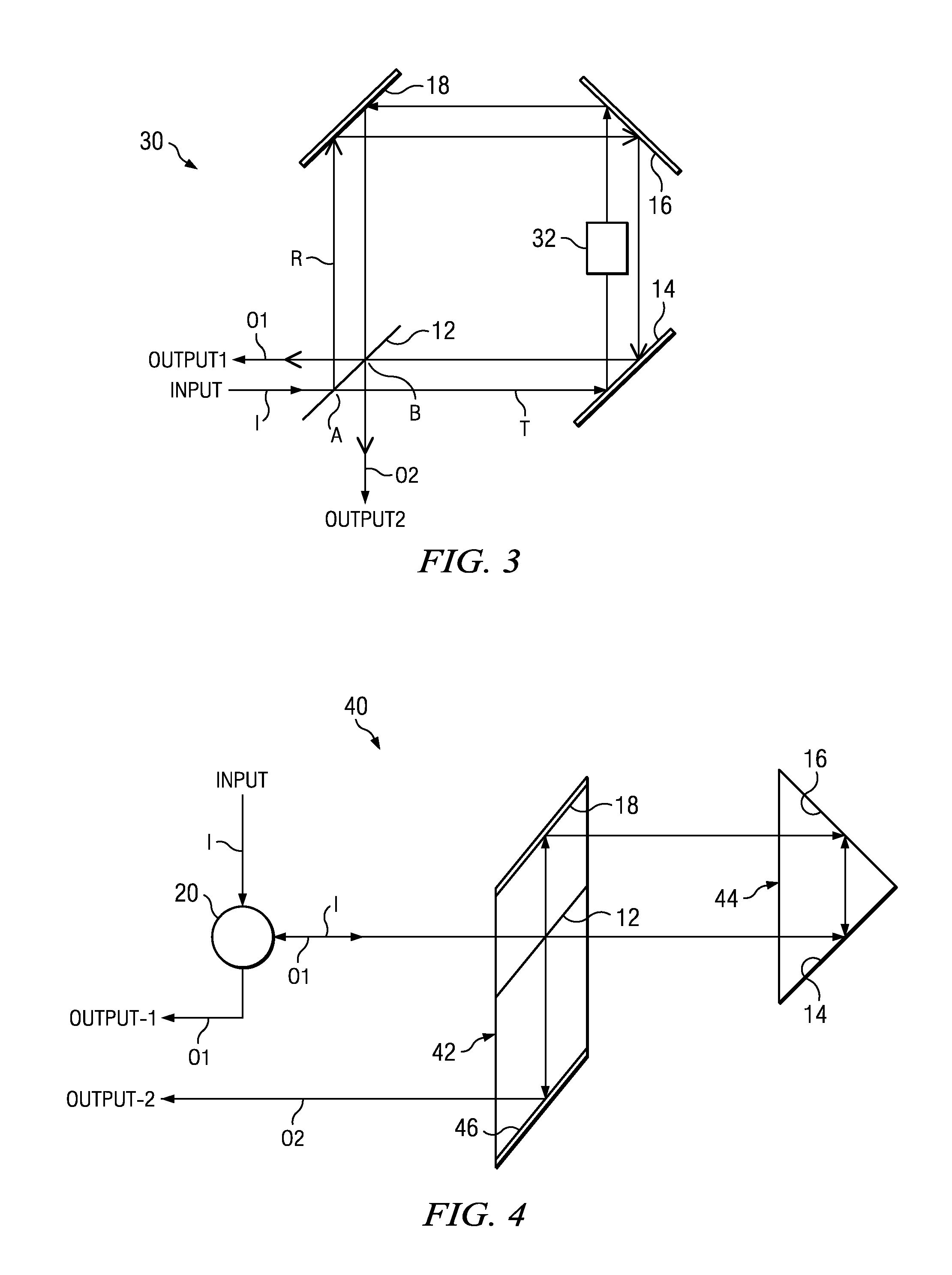
[0023]Referring to the figures, wherein like reference numerals and symbols are used throughout to refer to the same components, FIG. 3 illustrates schematically a common-path delay-line interferometric (DLI) demodulator 30 in Sagnac configuration according to the invention. The device includes the same optical elements of the interferometer of FIG. 2, wherein the first mirror 14 is shifted closer to the beam-splitting surface 12, in relation to the configuration of FIG. 1, in order to cause the transmitted beam T and the reflected beam R to impinge on the beam-splitting surface and interfere at a point B different from the point A where the incoming beam I impinges on the same surface. As mentioned, due to the extreme proximity of the transmitted and reflected beam paths, the two beams still travel essentially along a common path (though in opposite directions). However, the separation of the two beam paths allows access to each beam individually, thereby giving the opportunity to ...


PUM

PropertyMeasurementUnit
optical path differenceaaaaaaaaaa
phaseaaaaaaaaaa
thermal driftaaaaaaaaaa

Abstract

A DPSK demodulator is implemented in Sagnac interferometer configuration with a delay line element introduced in one or both of the optical paths of the transmitted and reflected beams. Because the two reflected and transmitted beams travel on the same optical path (though in opposite directions), the Sagnac interferometer provides all the advantages of a common-path interferometer, is thermally and mechanically stable, and the phase requirements are greatly reduced. In its simplest form, the Sagnac DPSK demodulator. In the preferred embodiment, the beam-splitting surface and one of the mirrors are combined into a rhomb beam-splitter structure and the other two mirrors into a right-angle prism. In a DQPSK embodiment, the input beam is split by an upfront beam splitter into two parallel beams that are then directed toward the rhomb-beam-splitter/right-angle-prism combination of the invention.

Description

RELATED APPLICATIONS[0001]This application is a Continuation-In-Part Application of Ser. No. 12 / 509,474, filed Jul. 26, 2009, which is based on and claims the priority of U.S. Provisional Application Ser. No. 61 / 084,229, filed Jul. 28, 2008.BACKGROUND OF THE INVENTION[0002]1. Field of the Invention[0003]This invention relates to differential phase-shift keying (DPSK) in telecommunication. More specifically, it relates to methods in DPSK for converting a phase-keyed signal to an intensity-keyed signal.[0004]2. Description of the Prior Art[0005]Phase-shift keying (PSK) is a digital modulation scheme that conveys data by changing, or modulating, the phase of a reference signal (the carrier wave). Any digital modulation scheme uses a finite number of distinct signals to represent digital data. In the case of PSK, a finite number of phases is used. Each of these phases is assigned a unique pattern of binary bits. Usually, each phase encodes an equal number of bits. Each pattern of bits f...

Claims


Application Information

Patent Timeline
Patent Type & Authority Patents(United States)
IPC IPC(8): G02F2/00G02B1/10
CPCH04B10/677G02F2001/211G02F1/211
Inventor HSIEH, YUNG-CHIEHAI, CHIAYU
Owner OPTOPLEX CORP
Why Eureka
Try Eureka