Multi-purpose grill stand

a multi-purpose, grilling technology, applied in the direction of lighting and heating equipment, domestic stoves or ranges, tableware, etc., can solve the problems of inability to easily remove and carry such cooking vessels, limiting the versatility of permanent attachment of cooking vessels and grills, and generally not being able to utilize a variety of other custom-made or readily available store-bought cooking vessels and utensils. , to achieve the effect of simple, durable and robust construction, and low manufacturing

Inactive Publication Date: 2012-09-25
KOCHER CHARLES
View PDF35 Cites 22 Cited by
  • Summary
  • Abstract
  • Description
  • Claims
  • Application Information

AI Technical Summary

Benefits of technology

[0005]It is also an object of this invention to provide an adjustable cooking vessel handle support mechanism that can accommodate and be adapted to different angles and configurations of handles and support bars in their relation to the horizontal plane of the cooking surfaces of the cooking, grilling and roasting vessels and devices. This manual adjustment mechanism allows the cook to align the horizontal plane of the cooking surfaces to a level that is perpendicular to the vertical forces of gravity, thus keeping the food balanced on an even plane in relation to the hearth and preventing it from rolling off the cooking surface.
[0019]The main body of the cooking vessel handle support mechanism can be constructed of, but not limited to, a U-shaped configuration where the two long ends of the U-shaped configuration are parallel and symmetrical with the two wider dimensions of the flat bar stock facing each other. The U-shaped configuration of the cooking vessel handle support mechanism can be achieved, but is not limited to, by bending a piece of flat bar stock at its midpoint by 180 degrees or by connecting two parallel pieces of flat bar stock with an end cap or spacer block, possibly using a welding, soldering, bolting or riveting process. The distance between the two parallel members is slightly greater than the thickness of the vertical central post so that the central post can receive the cooking vessel handle support mechanism. This sliding cooking vessel handle support mechanism has a primary locking device to allow or prevent the device from sliding along the vertical central post, or being locked at any desired vertical position along said post. This primary locking device provides a clamping mechanism such as, but is not limited to, a spring-loaded locking device, a threaded thumb screw or screw device, a threaded and bent handlebar or any other suitable locking device. The cooking vessel handle support mechanism also provides a rest and holding mechanism for a wide variety of cooking vessels, their handles, support bars and accessories. This holding mechanism is comprised of two parallel, rigidly mounted, support pins which extend laterally in a horizontal plane from one side of the cooking vessel handle support mechanism. These pins are spaced in such a manner that allows a cooking vessel to be supported in a cantilever manner This configuration allows the back end part of the cooking vessel handle to be slipped under the rear-positioned support pin and the front part of the handle to be positioned over the front-positioned support pin, thus suspending the cooking vessel by its handle in a cantilever manner over the heat source. The weight of the main component of the cooking vessel, mounted in this cantilever manner, applies a forward and downward rotating torque to said cooking vessel handle support mechanism, thus frictionally engaging parts of the cooking vessel handle support mechanism with the surface of the upright central post, consequently locking the cooking vessel handle support mechanism securely to the upright central post, creating a secondary frictional locking mechanism. The design with respect to position and length and construction of the two support pins, allows the cook to easily adjust the cooking vessel laterally pivotal around a vertical axis and transversely from front to back over the heat source. Each support pin has a slight upward and a downward bend, respectively, on its first and 2nd ends, to prevent the cooking vessel handle from accidently sliding off the cooking vessel handle support mechanism support pins.

Problems solved by technology

These permanently attached cooking vessels and grills offer limited versatility due to their size, configuration, lack of mobility and fixed angle in relation to the hearth.
These single-use cooking vessel support assemblies deny the cook the versatility of utilizing a variety of other custom-made or readily available store-bought cooking vessels and utensils.
It is generally not possible to easily remove and carry such cooking vessels, as shown in prior art, to offer cooked food to guests, or to carry such vessels to the table for serving.
Some of the support assemblies shown in the prior art are heavy and bulky and not suitable for easy transport and storage.

Method used


Image

  • Multi-purpose grill stand
  • Multi-purpose grill stand
  • Multi-purpose grill stand

Examples


Embodiment Construction

)

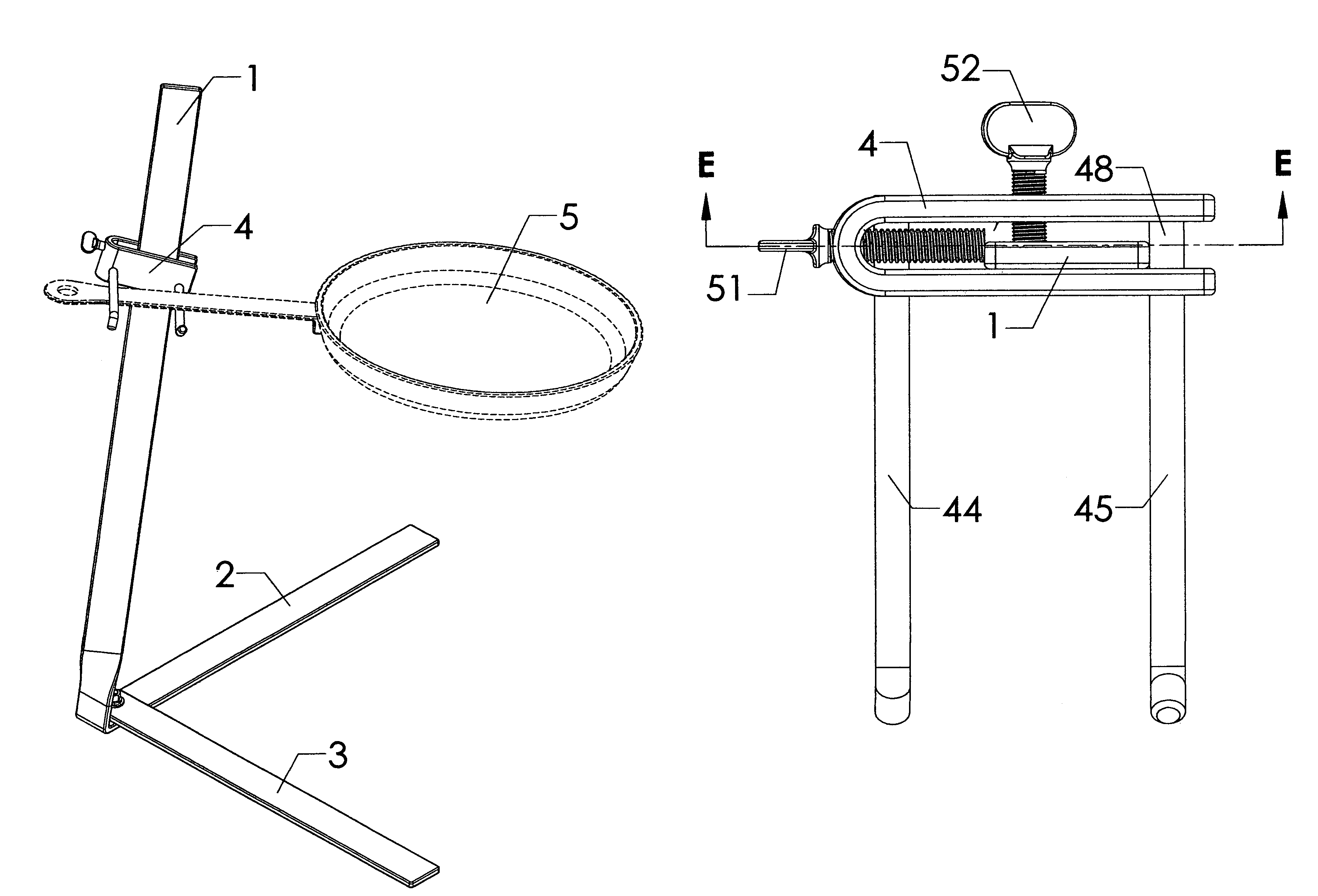
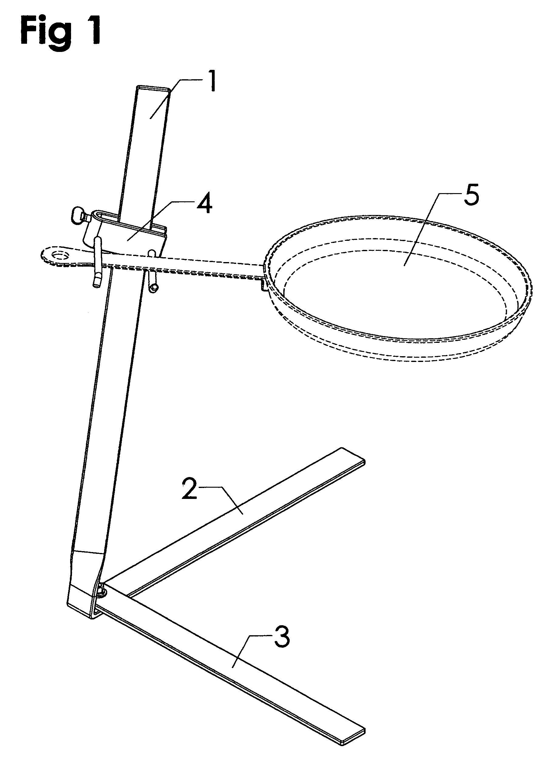
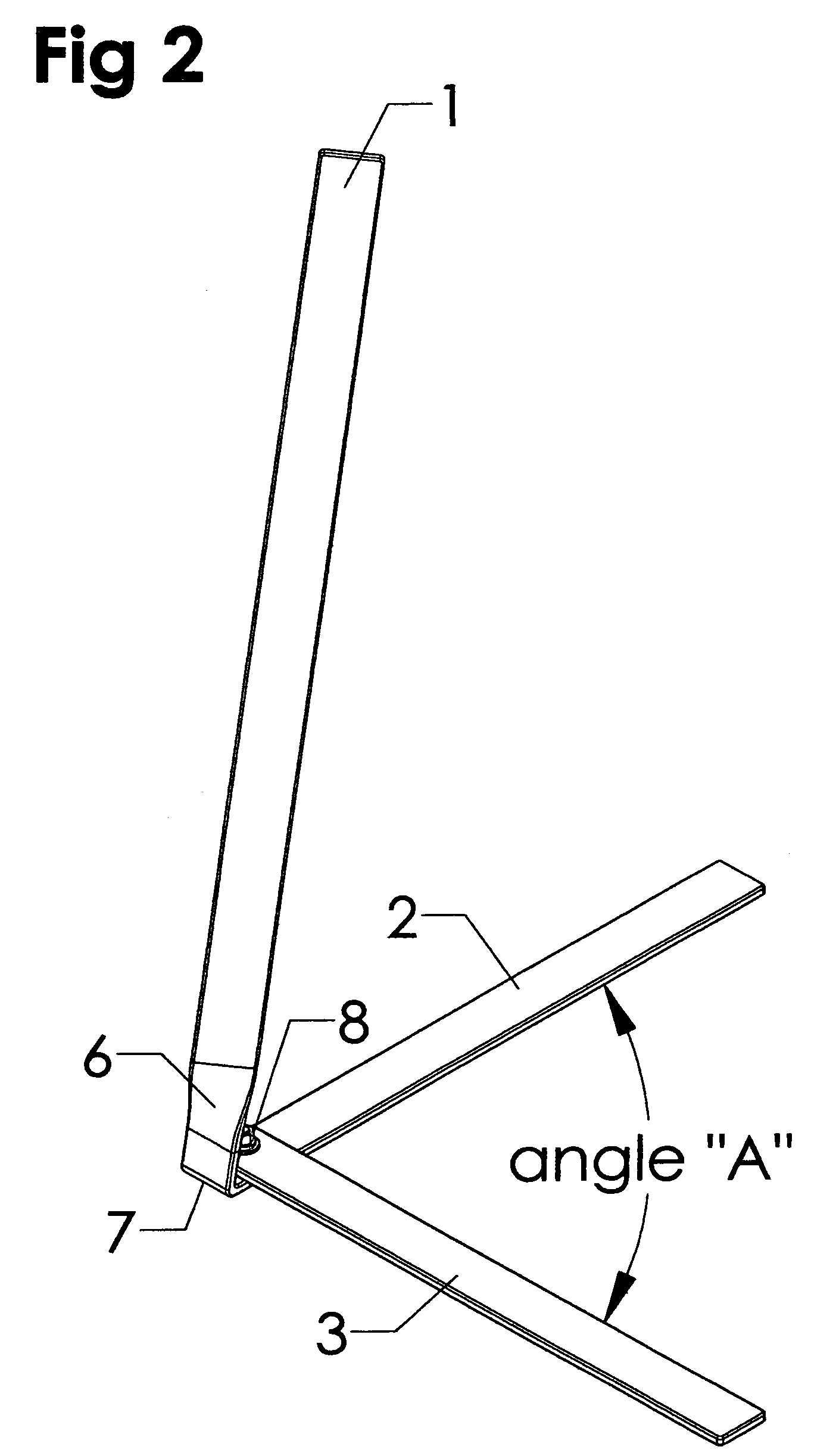
[0042]In the form of construction shown in FIG. 1, an adjustable cooking vessel holding device is composed of an upright member 1, a support foot 2, a second support foot 3 and a cooking vessel handle support mechanism 4. In this preferred embodiment, the upright member 1 is constructed from a flat-bar stock of approximately a one-to-six ratio in relation to its thickness and width and has at its lower extremity an approximately 45 degree twist 6, as shown in FIG. 2, and an approximately 90 degree bend 7 between the lowest extremity of the upright member 1 and the support foot 2. The approximately 90 degree bend 7 allows the upright member 1 and the support foot 2 to be constructed out of one piece of flat bar stock, making support foot 2 an extension of upright member 1. The bend 7 may be slightly more than 90 degrees, thus positioning the upright member 1 at a slight decline in relation to the vertical. This slight decline positions the center of gravity of a cooking vessel 5, as...


PUM


Abstract

A cooking utensil support apparatus used for the cooking of food in a cooking utensil over a heat source, such support apparatus having stand and a cooking utensil handle support member adjustably positioned on such stand with angle adjustment means for adjusting the angle of the cooking utensil handle support member and the handle supported therein of such cooking utensil.

Description

[0001]This application claims priority and benefit of a provisional patent application entitled Multi-purpose Grill Stand, Application No. 61 / 191,523 filed Sep. 10, 2008, now pending.FIELD OF INVENTION[0002]This invention relates to a grilling and cooking vessel support apparatus to be used with an open fire source, such as an indoor or outdoor fireplace, cooking hearth, woodstove, fire-ring or fire-pit, camp or beach fire, park and camping grills and the like and more particularly to a freestanding portable, moveable and foldable grilling and cooking vessel support apparatus that is fully adjustable horizontally, vertically, laterally, transversely and pivotally in the vertical and horizontal plane with respect to the hearth, and more particularly to a freestanding, portable and foldable grilling and cooking vessel support apparatus that offers a fully adjustable support mechanism in order to receive, support and balance a wide variety of store-bought or custom-made cooking, grilli...

Claims


Application Information

Patent Timeline
Patent Type & Authority Patents(United States)
IPC IPC(8): F16L3/00
CPCA47J33/00A47J37/07A47J2037/0777
Inventor KOCHER, CHARLES
Owner KOCHER CHARLES
Why Eureka
Try Eureka