Retaining wall system

a technology of retaining walls and walls, applied in the direction of excavation, artificial islands, foundation engineering, etc., can solve the problems of many blocks, heavy weight of relative small modules, and limited degree of setback they are capable of attaining, so as to simplify and optimize the casting and demolding process, light weight, and the effect of reducing weigh

Inactive Publication Date: 2012-09-25
GREENWALL VENTURES LLC
View PDF98 Cites 6 Cited by
  • Summary
  • Abstract
  • Description
  • Claims
  • Application Information

AI Technical Summary

Benefits of technology

[0008]Among the several aspects and features of the present invention may be noted the provision of an improved retaining wall building block which has the advantages of relatively light weight, a simplified and efficient casting and demold process, and the incorporation of features for attachment of lifting machinery, reinforcing structures, retention of fill material between adjacent blocks in a course, creating curved retaining walls, and anchoring structures without disadvantages of dry cast concrete. As is known in the art, because wet cast concrete is supported in a mold during the cure process, only the minimum amount of concrete to support the end structure need be used. By contrast, because dry cast concrete blocks are extruded and must be relatively dry, the block must be more robust to maintain its shape prior to curing, while still in the green or plastic state. Thus, wet cast concrete allows reduction in materials used, resulting in a thinner and lighter block. Its reduced weight requires less shipping and handling effort and expense.
[0015]Generally, in one embodiment a retaining wall building block of the present invention comprises a base, a generally upright face wall extending upward from the base, and two generally upright side walls extending upward from the base and generally rearward of the face wall. A fill receiving cavity is defined by inner surfaces of the base, face wall, and side walls for receiving fill material such as earth during construction of a retaining wall. Because of the inherent efficiency in the wet cast concrete process, the base face wall, and side walls may each have a mean thickness which is less than approximately 20% of the width of the block to maximize the volume of the fill receiving cavity, the width of the block being defined by the distance between outer surfaces of the side walls.
[0016]The system of the present invention utilizes of injection molded forms, including an insert, preferably of polymer material, which mates with the mold base to form a complete mold to cast the concrete portion of the block. The formed wet concrete portion then becomes bonded to the insert to form a composite polymer / concrete block with the insert forming the interior cavity surface. The insert also preferably comprises pre-formed slots to receive a drop-in structural support which lends stability to the block for building curved walls. The slots also may receive a lifting bracket to facilitate connection with lifting machinery for handling and transporting blocks. The slots may mate with snap-in connectors to connect the block to geo-grid material which is secured in the soil behind the blocks to aid in placement of blocks on slopes. The insert may also include a connection hub for attaching to an anchoring grid.

Problems solved by technology

Because of this high density, even relatively small modules can be quite heavy.
Many blocks, such as those disclosed in U.S. Pat. No. 4,671,706, are limited in the degree of set back they are capable of attaining.

Method used


Image

  • Retaining wall system
  • Retaining wall system
  • Retaining wall system

Examples


Embodiment Construction

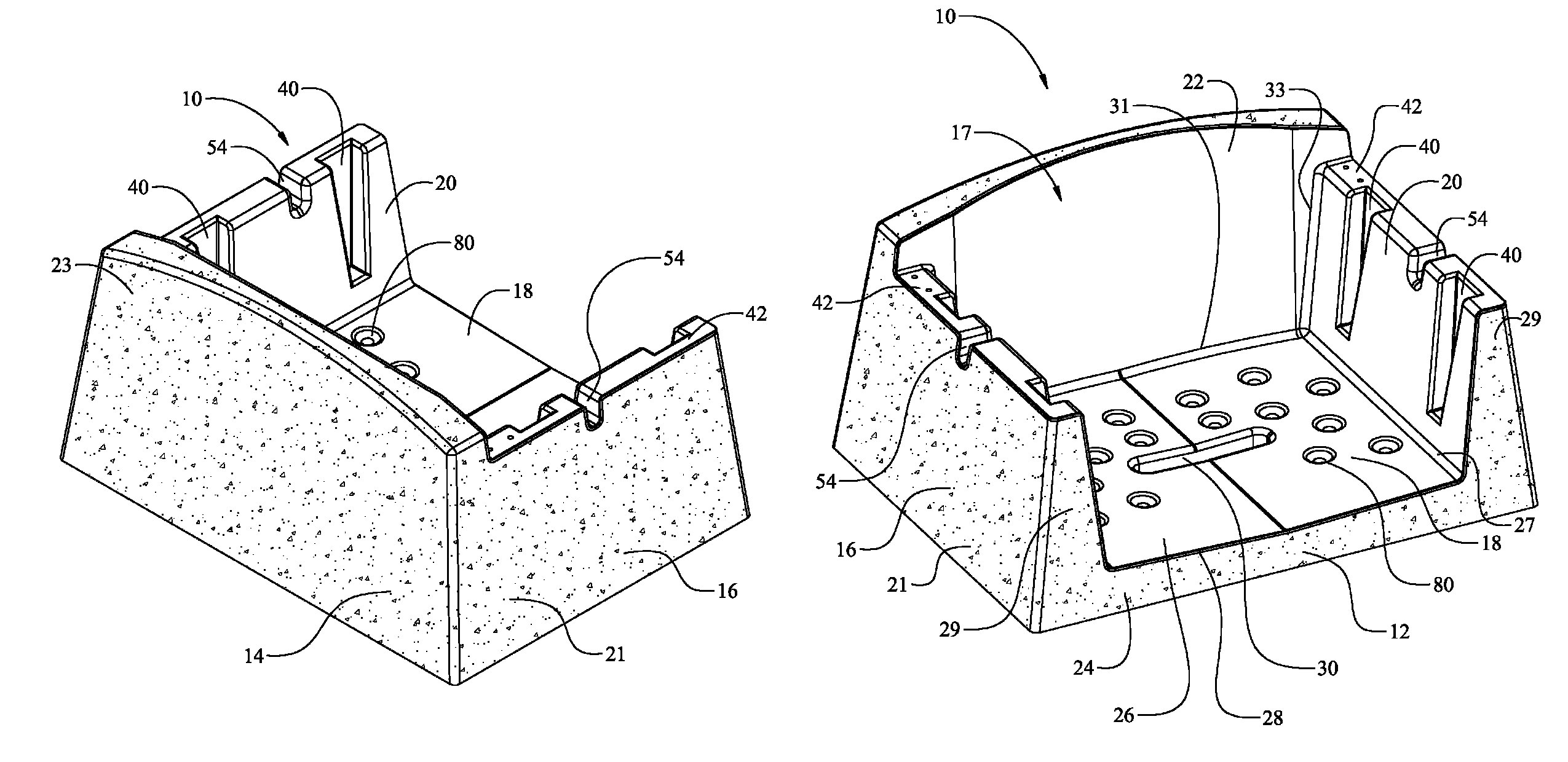
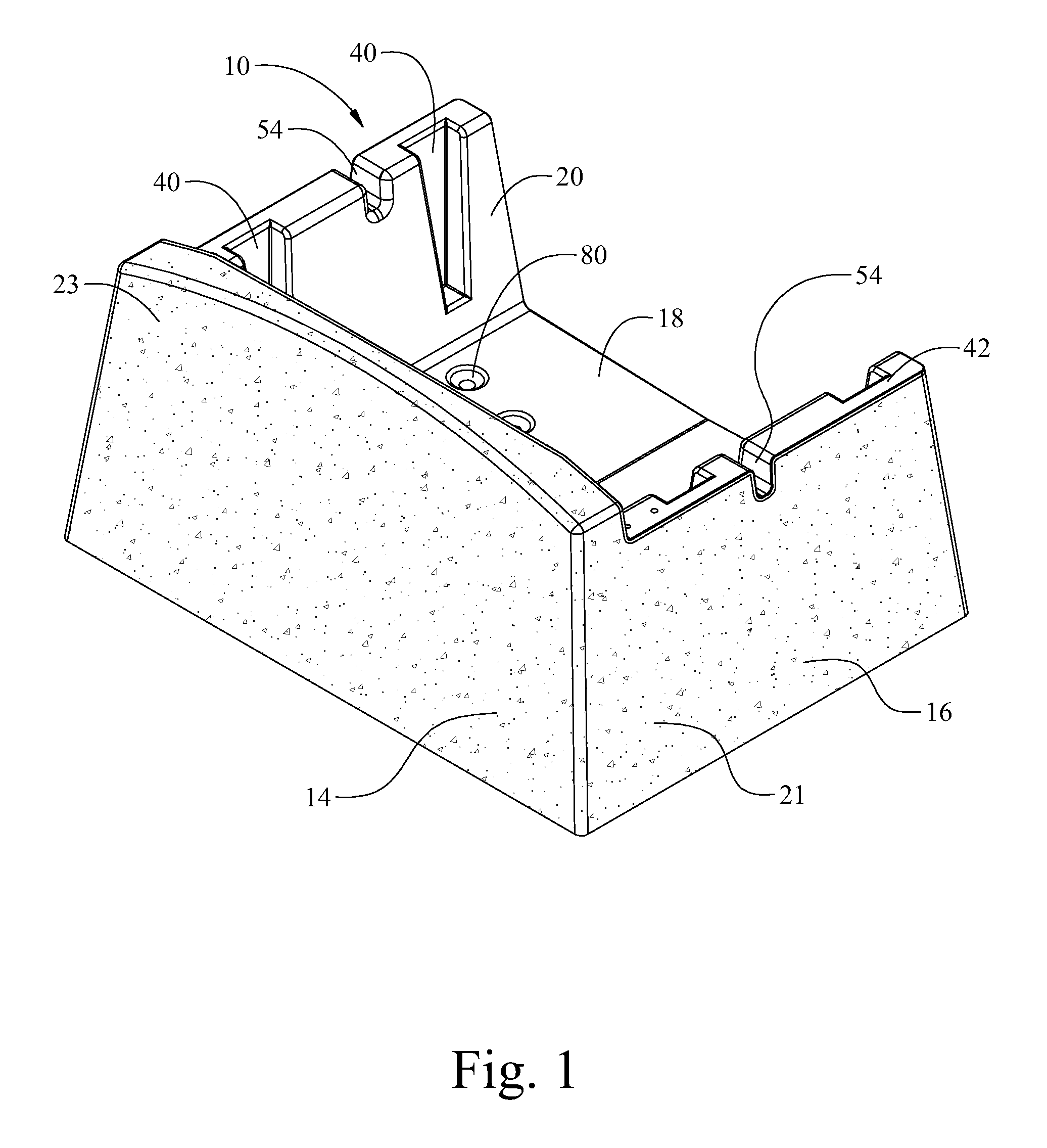
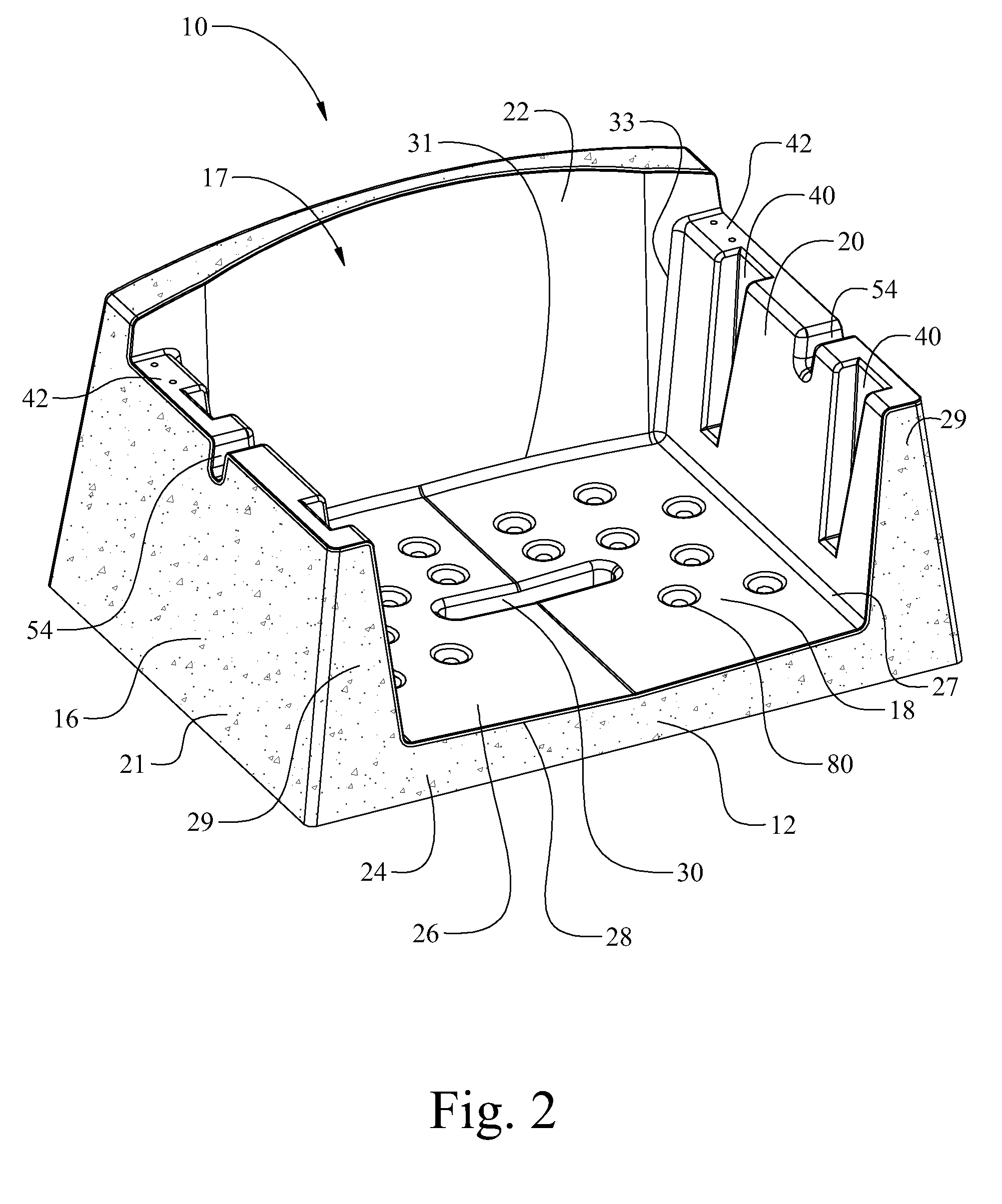
[0063]FIGS. 1-9 illustrate one preferred embodiment of the building block of the present invention, generally indicated in its entirety by the reference numeral 10. In general, building block 10 comprises base 12, generally upright face wall 14 extending upward from the base, and two generally upright side walls 16 extending upward from the base and generally rearward of the face wall. Base 12 has an inner surface 18 and an outer surface 19, sidewalls 16 have an inner surface 20 and an outer surface 21, and face wall 14 has an inner surface 22 and an outer surface 23. Fill receiving cavity 17 (FIGS. 2 & 4) is defined by base inner surface 18, side wall inner surfaces 20 and face wall inner surface 22 and receives fill material such as earth, sand, aggregate, mulch and the like during construction of a retaining wall.

[0064]As shown in FIGS. 1-9, building block 10 does not possess a rear wall but it is to be understood that it may optionally include a rear wall extending upward from t...


PUM

PropertyMeasurementUnit
set back anglesaaaaaaaaaa
βaaaaaaaaaa
βaaaaaaaaaa

Abstract

Retaining wall building blocks for receiving fill material during construction of a retaining wall, retaining walls constructed with the building blocks and methods of manufacture of the building block wherein the block comprises a cast cement body having a base, a generally upright face wall extending upward from the base, two generally upright side walls extending upward from the base and generally rearward of the face wall, the base, upright face wall, and side walls each having an inner and an outer surface, the side walls each having a top and a rearward most end, and a fill receiving cavity defined by base inner surface, side wall inner surfaces and face wall inner surface for receiving fill material, the fill receiving cavity having a volume wherein a ratio of the volume of the fill receiving cavity to the volume of the retaining wall building block is at least 0.75:1, respectively.

Description

[0001]This application claims priority from U.S. patent application Ser. No. 61 / 089063, filed Aug. 15, 2008, the entire contents of which are incorporated herein by reference.FIELD OF THE INVENTION[0002]The present invention relates to a retaining wall system comprised of units, sometimes referred to as building blocks or modules comprising a cementitious or polymeric composition, and more specifically, to a retaining wall system comprised of building blocks or modules having a planter compartment.BACKGROUND OF THE INVENTION[0003]Currently, a wide variety of building blocks or modules are available for construction of retaining walls to hold back or support earth or other fill material, each tailored to a particular use. Generally, a retaining wall may be constructed with building blocks made from natural sources such as timber, granite or stone, or with man-made materials such as concrete. Man-made materials typically cost less than most natural materials and are more versatile sin...

Claims


Application Information

Patent Timeline
Patent Type & Authority Patents(United States)
IPC IPC(8): E04C2/04E02D3/02
CPCE02D17/20E04C1/395E02D29/025
Inventor WOOLBRIGHT, MARK
Owner GREENWALL VENTURES LLC
Why Eureka
Try Eureka