Piston pump

a technology of piston pump and piston cylinder, which is applied in the direction of positive displacement liquid engine, liquid fuel engine, braking system, etc., can solve the problems of low production efficiency, low efficiency, and high cost of known piston pump construction, so as to reduce flow loss, reduce cost, and reduce the effect of structural spa

Inactive Publication Date: 2012-09-25
ROBERT BOSCH GMBH
View PDF13 Cites 7 Cited by
  • Summary
  • Abstract
  • Description
  • Claims
  • Application Information

AI Technical Summary

Benefits of technology

[0038]The foregoing relates to the preferred exemplary embodiments of the invention, it being understood that other variants and embodiments thereof are possible within the spirit and scope of the invention, the latter being defined by the appended claims.
[0007]Preferably, the fixation lugs are each spaced equally apart from one another along a circumference of the valve body. It should be noted that especially preferably, three or four fixation lugs are provided. As a result, an adequate cross-sectional area for the inflow of fluid can be furnished between the various fixation lugs.
[0008]In an especially preferred feature of the invention, each of the fixation lugs includes one step. The step serves as a stop for a face end of the piston, so that upon mounting of the valve body onto the piston, a defined position of the valve body on the piston is always obtained. As a result, errors in assembly can also be avoided. Moreover, as a result of the graduation, a press fit between the piston and the valve body can be achieved.
[0009]To make especially economical production possible, the piston is preferably a cylindrical roll of a solid material, in particular a metal material.
[0010]To make fast and simple assembly possible, a fastening of the fixation lugs to the piston is preferably done by nonpositive engagement, in particular via a press fit.
[0011]The valve body is especially preferably made from a plastic material. As a result, production costs can be reduced, since the valve body can be produced economically by an injection-molding process.
[0014]The present invention further relates to a piston pump for conveying fluids, including a piston and a pressure chamber that is located between an inlet valve and an outlet valve. The inlet valve includes a valve body, a closing element, and a prestressing device for prestressing the closing element; the prestressing device of the inlet valve includes many elastic prestressing elements. The elastic prestressing elements take on a function of a restoring spring for the inlet valve. The prestressing elements preferably have an undercut for holding the closing element and are moreover preferably formed in one piece with a valve body of the inlet valve. The prestressing elements are preferably made from a plastic material.
[0013]In an alternative feature, the prestressing device includes many elastic prestressing lugs, which retain the closing element. By elastic deformation of the prestressing lugs, the inlet valve can be opened. Beyond a predetermined opening pressure, the prestressing lugs deform, and they close the inlet valve again once the opening pressure has dropped below the predetermined value. For holding the closing element, the prestressing lugs preferably have an undercut. Also preferably, the prestressing lugs are formed in one piece with the valve body.
[0014]The present invention further relates to a piston pump for conveying fluids, including a piston and a pressure chamber that is located between an inlet valve and an outlet valve. The inlet valve includes a valve body, a closing element, and a prestressing device for prestressing the closing element; the prestressing device of the inlet valve includes many elastic prestressing elements. The elastic prestressing elements take on a function of a restoring spring for the inlet valve. The prestressing elements preferably have an undercut for holding the closing element and are moreover preferably formed in one piece with a valve body of the inlet valve. The prestressing elements are preferably made from a plastic material.
[0016]Also preferably, a sealing element for sealing off the pressure clamber from a low-pressure zone of the piston pump is additionally disposed on the valve body.

Problems solved by technology

However, this requires metal-cutting machining of the piston, which is very complicated.
It has furthermore been found that because of the delivery by the piston and the attendant relatively long travel distances for delivering the fluid, flow losses occur.
Hence the known piston pump is relatively complicated in its construction and expensive to manufacture.

Method used


Image

  • Piston pump
  • Piston pump
  • Piston pump

Examples


Embodiment Construction

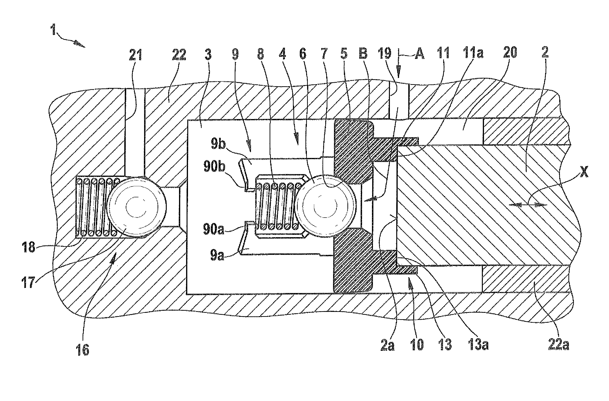
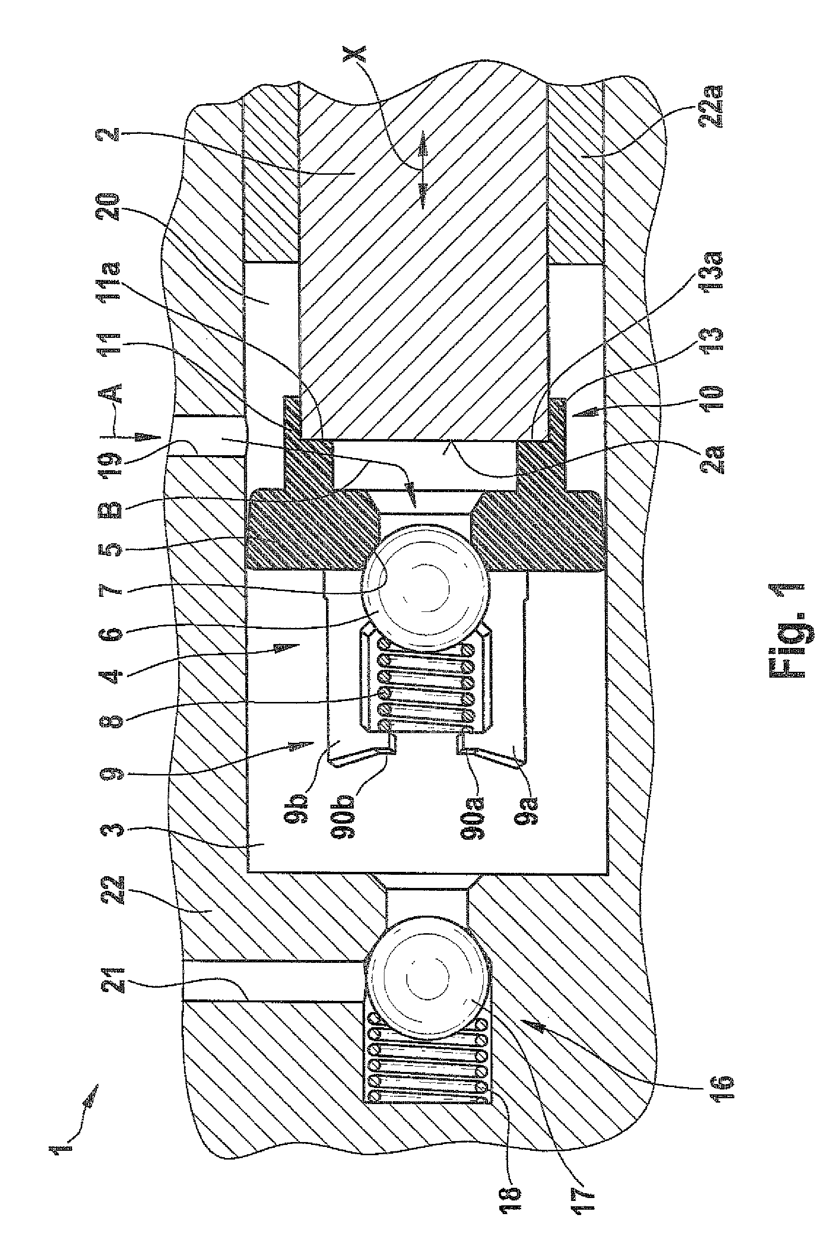
[0024]A piston pump 1 in a first exemplary embodiment of the invention will be described below with reference to FIGS. 1 through 5.

[0025]As can be seen from FIG. 1, the piston pump 1 includes a piston 2, which is made from a solid material as a cylindrical roll. The piston 2 is guided movably back and forth (double arrow X in FIG. 1) on a housing 22 in a sleeve 22a and is driven for instance by means of a cam for example (not shown). The piston pump 1 furthermore includes an inlet valve 4, an outlet valve 16, and a pressure chamber 3 disposed between the inlet valve 4 and the outlet valve 16.

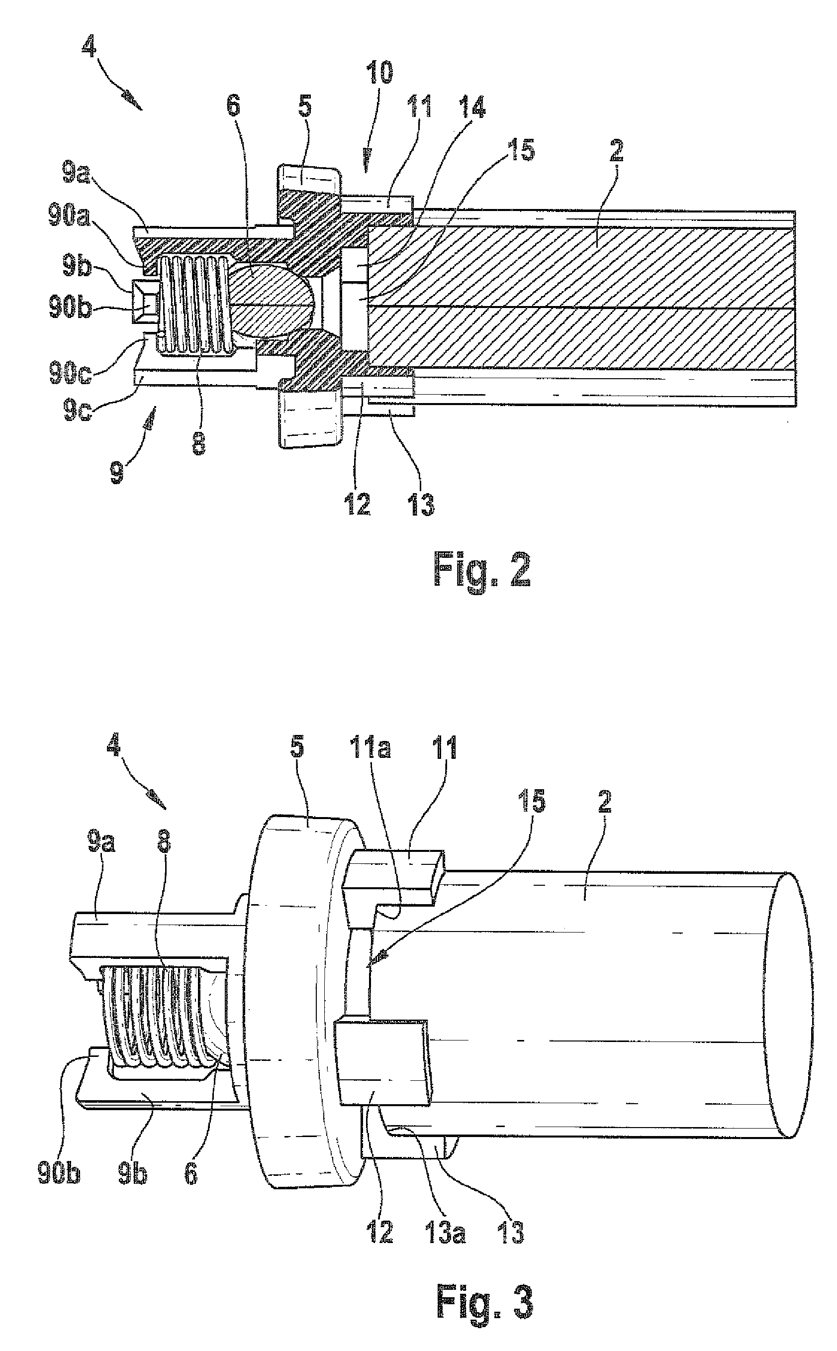
[0026]The inlet valve 4 includes a valve body 5, which is made from a plastic material. The inlet valve 4 furthermore includes a closing element 6, which in this exemplary embodiment is a ball. The closing element 6 either seals off a valve seat 7 that is formed on the valve body 5 or opens the valve seat. The closing element 6 is prestressed against the valve seat 7 by means of a cylindrical sp...


PUM


Abstract

The invention relates to a piston pump for conveying fluids. The piston pump includes a piston, and a pressure chamber located between an intake valve and a discharge valve. The intake valve is arranged between the pressure chamber and a low-pressure zone of the piston pump. The intake valve has a valve body, a closing element, a device for preloading the closing element, and a device for fastening the intake valve to the piston. The fastening device encompasses at least two fastening elements which protrude from the valve body toward the piston. The fastening elements are positioned at a distance from one another, and are fitted with inlets therebetween for supplying fluid. The invention further relates to a piston pump having an intake valve without a spring-biased element.

Description

CROSS-REFERENCE TO RELATED APPLICATION[0001]This application is a 35 USC 371 application of PCT / EP 2007 / 054952 filed on May 22, 2007.BACKGROUND OF THE INVENTION[0002]1. Field of the Invention[0003]The present invention relates to a piston pump for conveying fluids, and in particular to a piston pump for conveying liquids in vehicles, such as brake fluid or fuel.[0004]2. Description of the Prior Art[0005]Piston pumps in various embodiments are known from the prior art. In vehicles, piston pumps are used for instance as fuel pumps, or as pumps for supplying pressure to brake systems. A known piston pump, between an inlet valve and an outlet valve, has a work or pressure chamber, in which a pressure is built up by means of a linear motion of a piston. In order to have the most compact possible construction, the fluid is delivered to the inlet valve through a plurality of radial bores and a longitudinal bore in the piston. However, this requires metal-cutting machining of the piston, wh...

Claims


Application Information

Patent Timeline
Patent Type & Authority Patents(United States)
IPC IPC(8): F04B39/10F04B53/12
CPCB60T8/4031F04B1/0452F04B53/126F04B1/04F04B53/12
Inventor BOLLWERK, ANDRESCHULLER, WOLFGANGBELING, HORSTWAGNER, JUERGENSCHUESSLER, MICHAELHALLERMANN, STEFAN
Owner ROBERT BOSCH GMBH
Why Eureka
Try Eureka