
Connector having a lock mechanism for keeping a socket and a header coupled, and method for manufacturing the connector

a lock mechanism and connector technology, applied in the field of connectors, can solve problems such as increased coupling force, and achieve the effects of enhancing assembling accuracy and product precision of the connector, facilitating the manufacturing process of the connector, and reducing the number of parts

Inactive Publication Date: 2012-09-25
PANASONIC CORP
View PDF14 Cites 37 Cited by
  • Summary
  • Abstract
  • Description
  • Claims
  • Application Information

AI Technical Summary

Benefits of technology

"The present invention provides a connector with lock mechanisms for keeping a socket and a header in a coupled state. The lock mechanisms are formed from the contacts of the sock and the header, which increases the coupling force between them. The lock mechanisms are positioned near the corners of the sock and the header, providing stability. The lock mechanisms are easy to assemble and help increase the productivity of the connector. The method for manufacturing the connector involves insert-molding the lock mechanisms with the sock and the header, simplifying the manufacturing process and improving the assembly accuracy and product precision. Overall, the present invention provides a small, simple, and easy-to-assemble connector with effective lock mechanisms."

Problems solved by technology

Thus, the coupling force of the lock mechanisms is added to the coupling force of the socket contacts and the header contacts, which results in an increased coupling force.

Method used


Image

  • Connector having a lock mechanism for keeping a socket and a header coupled, and method for manufacturing the connector
  • Connector having a lock mechanism for keeping a socket and a header coupled, and method for manufacturing the connector
  • Connector having a lock mechanism for keeping a socket and a header coupled, and method for manufacturing the connector

Examples


Embodiment Construction

[0030]The configuration of a connector in accordance with one embodiment of the present invention, which is provided with lock mechanisms for keeping a socket and a header in a coupled state, will be first described with reference to the accompanying drawings. It should be understood that the following description is not intended to limit the scope of the present invention but to increase the understanding of the embodiment of the present invention.

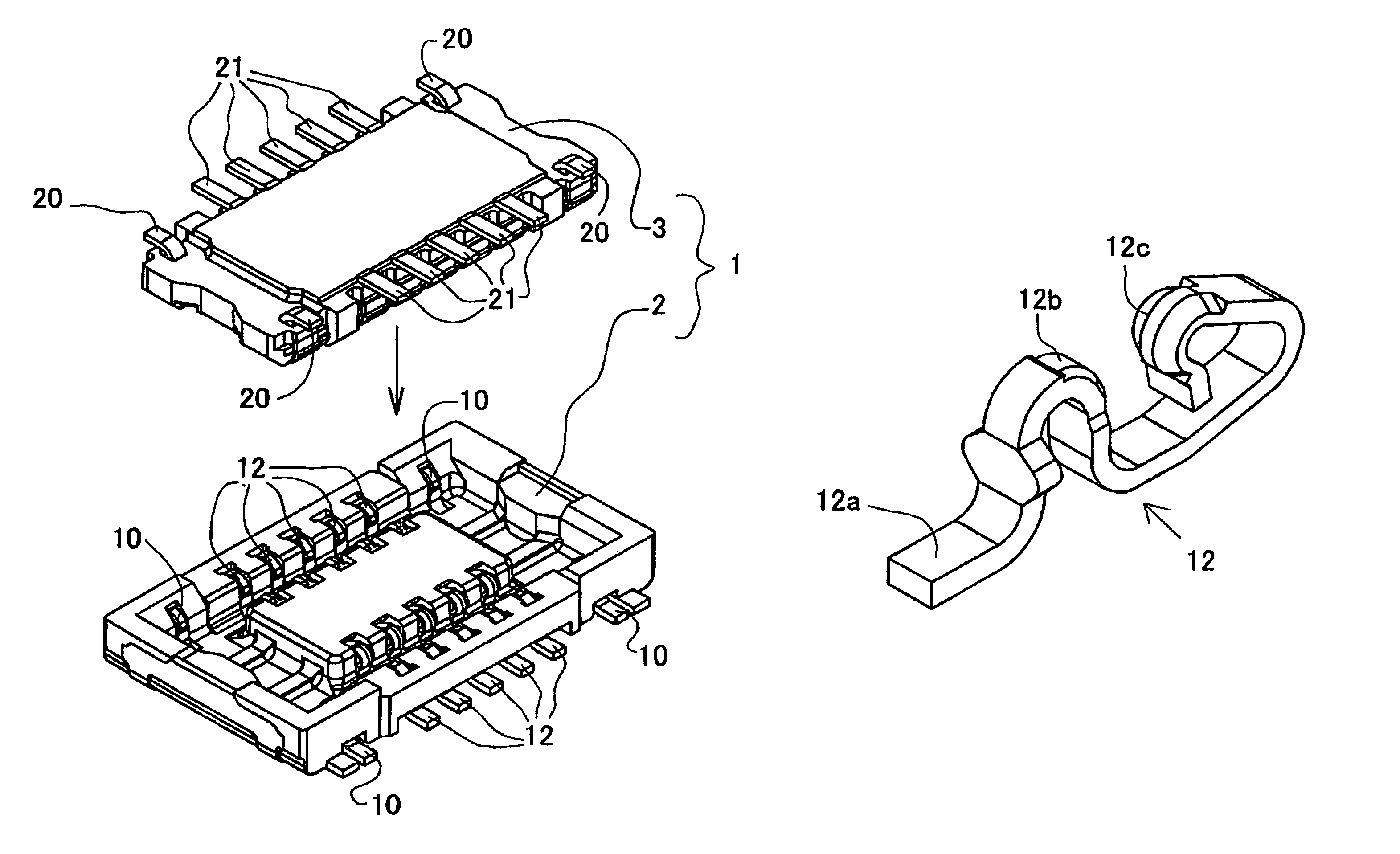
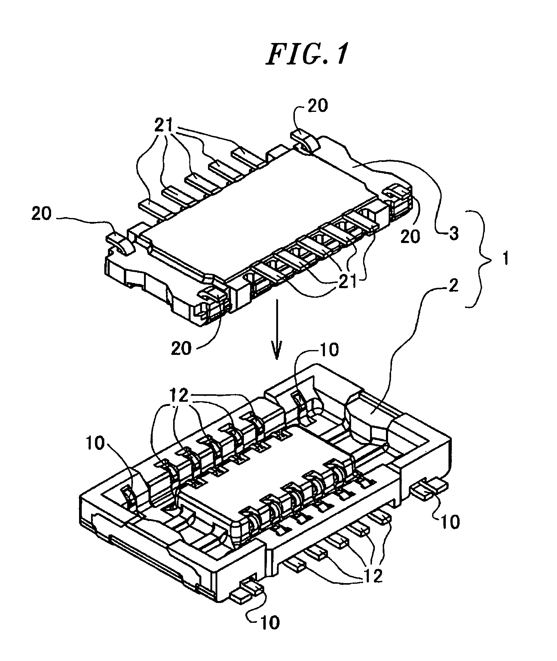
[0031]Referring to FIG. 1, a connector 1 in accordance with the embodiment of the present invention includes a socket 2 and a header 3. Description will be first made on the structures of the socket 2 and the header 3 and then the coupling method thereof.

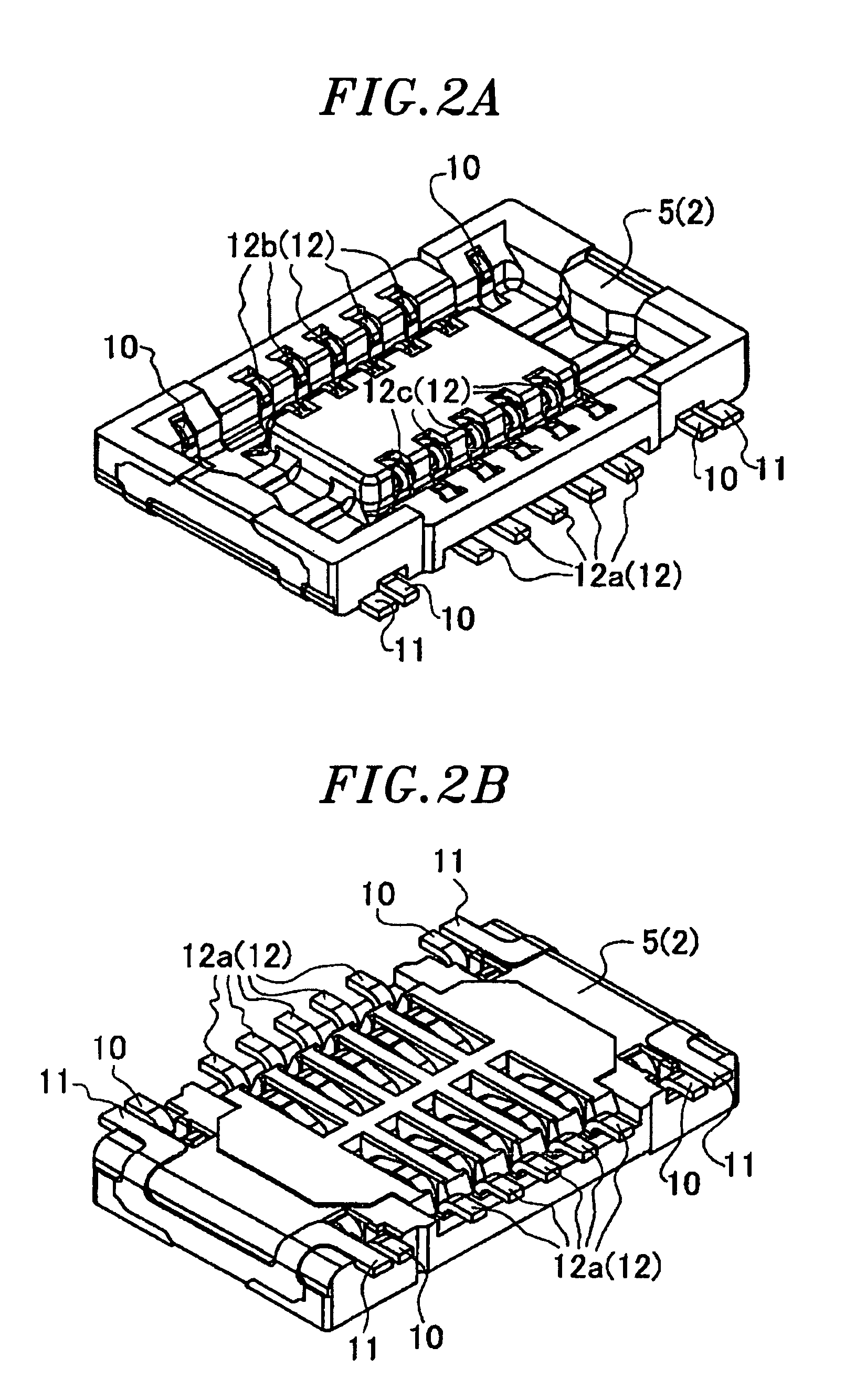
[0032]The socket 2 will be described first. FIG. 2A shows the front side of the socket 2, and FIG. 2B shows the rear side thereof. The socket 2 includes a socket body 5, socket-side lock clasps (lock mechanisms) 10, retainer portions (retainer mechanisms) 11 and socket contacts 12. As sho...


PUM

PropertyMeasurementUnit
shapeaaaaaaaaaa
rectangular shapeaaaaaaaaaa
heightaaaaaaaaaa

Abstract

A connector includes a socket having a generally rectangular shape, the socket including socket contacts, lock mechanisms and retainer mechanisms; and a header having a generally rectangular shape, the header including header contacts and lock mechanisms and being couplable with the socket. The lock mechanisms of the socket and the header are respectively formed from the socket contacts and the header contacts, the lock mechanisms of the socket being formed by cutting away a portion of the socket contacts. The lock mechanisms of the header also serve as retainer mechanisms thereof. The lock mechanisms of the socket and the header are arranged substantially in the same row as the socket contacts and the header contacts and positioned near four corners of the socket and the header, respectively. The lock mechanisms of the socket and the header are configured to keep the socket and the header in a coupled state.

Description

FIELD OF THE INVENTION[0001]The present invention relates to a connector provided with lock mechanisms for keeping the coupling state of a socket and a header which are coupled together and electrically connected to each other.BACKGROUND OF THE INVENTION[0002]In portable devices that are undergoing rapid reduction in size, it is required to reduce the height of a connector and contacts (or signal terminals), which is called profile reduction. However, the profile reduction is accompanied by reduction in the coupling force of a socket and a header. For that reason, the portable devices vulnerable to shocks caused by dropping or the like need to have a configuration that makes it hard to separate a socket and a header. A connector provided with lock mechanisms for keeping the socket and the header in a coupled state is disclosed in Japanese Patent Application Publication No. 2003-234150.[0003]In addition to the connector disclosed in Japanese Patent Application Publication No. 2003-23...

Claims


Application Information

Patent Timeline
Patent Type & Authority Patents(United States)
IPC IPC(8): H01R12/00H01R12/65H01R12/71H01R12/78H01R12/79H01R13/639H01R43/24
CPCH01R13/20H01R12/716H01R12/73
Inventor MIYAZAKI, YOJIOKURA, KENJI
Owner PANASONIC CORP
Learn More