
Beehive frame and comb foundation for controlling varroa mites

a technology of comb foundation and beehive, which is applied in the field of beehives, can solve the problems of not providing a means for economically treating multiple combs, not providing a means for monitoring the performance of mites, etc., and achieves the effects of reducing the cost of practicing in the u.s., improving performance, and reducing the cost of practicing

Inactive Publication Date: 2012-09-25
MITE ZAPPER
View PDF19 Cites 14 Cited by
  • Summary
  • Abstract
  • Description
  • Claims
  • Application Information

AI Technical Summary

Benefits of technology

"The present invention is an improvement over a previous mite control apparatus. It provides an effective and commercially profitable way to destroy varroa mites in bee colonies. The invention reduces the cost of practicing the previous patent and provides a means to monitor the performance of the mite control apparatus. It includes half portions of a frame and comb foundation, a heating unit, a power supply, an electronic control unit, a temperature sensor, and an optional diagnostic system. The invention can be used for multiple hives with individual electronic control units and temperature sensors. The exclusive rights to this invention are set forth in the patent text."

Problems solved by technology

Another shortcoming is that it does not provide a means for economically treating multiple hives.
Another shortcoming is that it does not provide a means for monitoring the performance of a mite control apparatus in a honey bee hive.

Method used


Image

  • Beehive frame and comb foundation for controlling varroa mites
  • Beehive frame and comb foundation for controlling varroa mites
  • Beehive frame and comb foundation for controlling varroa mites

Examples


Embodiment Construction

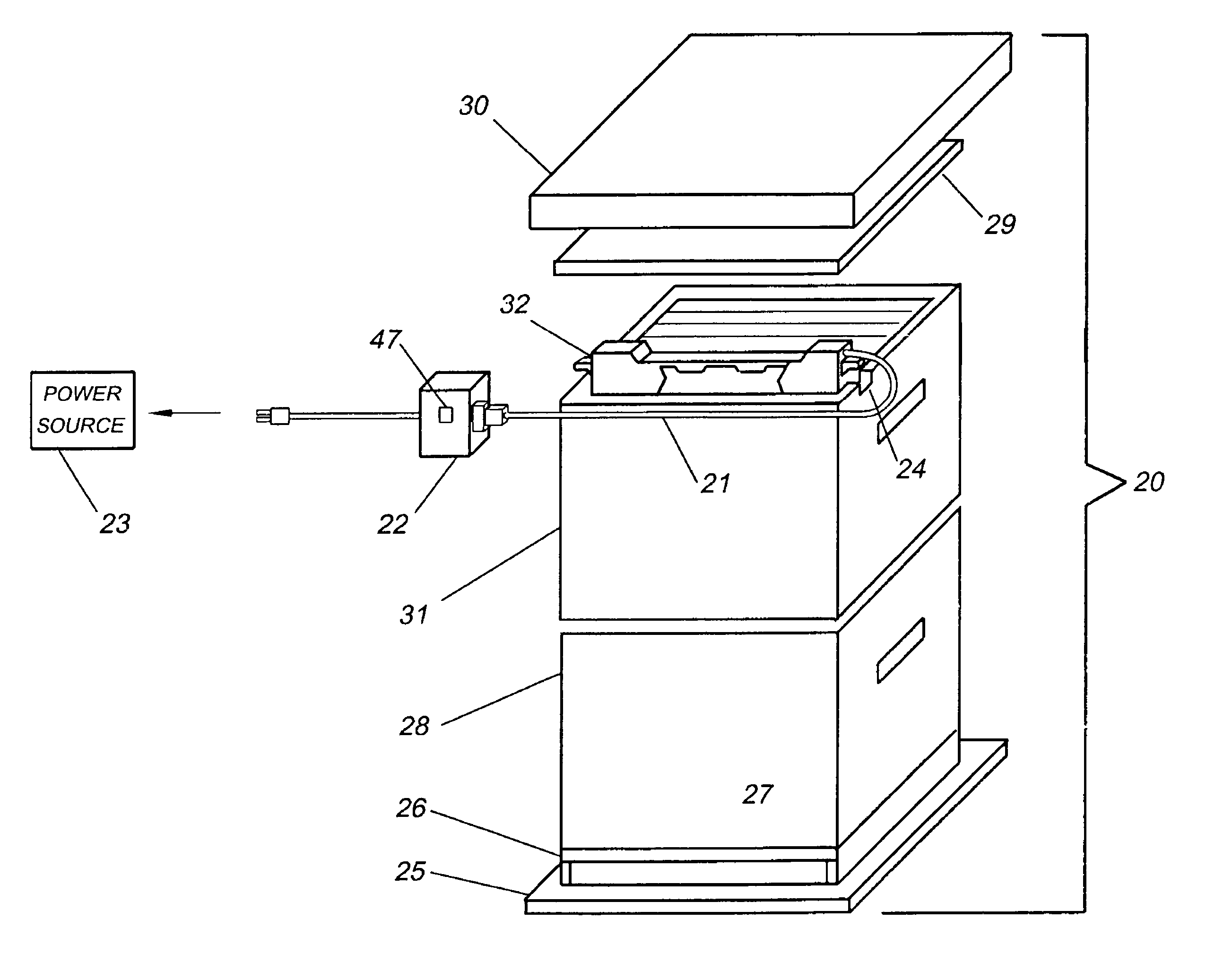
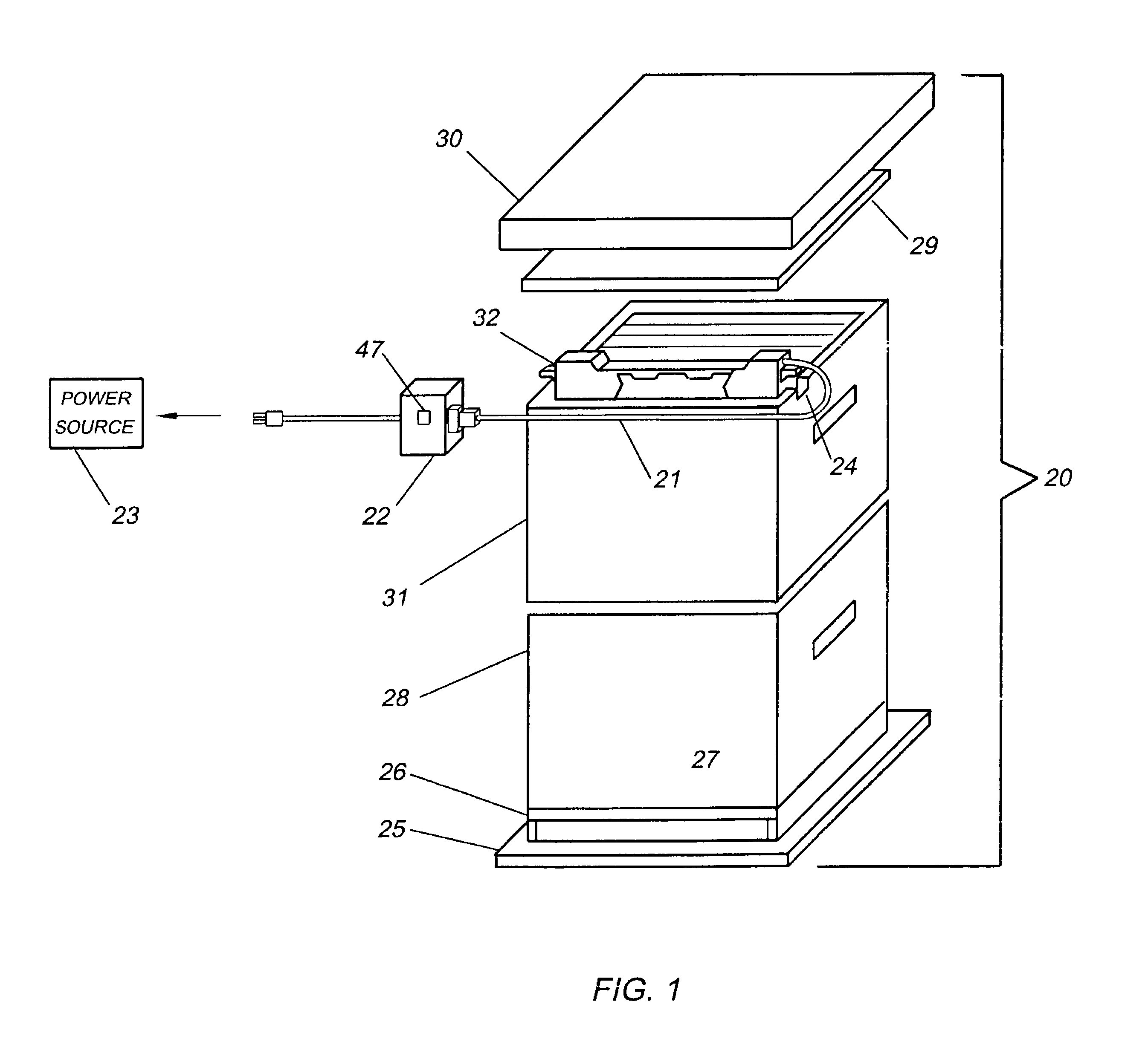
[0037]Referring now to the drawings wherein like numerals designate like and corresponding parts throughout the several views, in FIG. 1 is shown a beehive commonly referred to by the name of its inventor, Rev. Lorenzo Langstroth as a “Langstroth Hive”20 which incorporates the present invention.

[0038]One distinguishing feature of the hive 20 is an electrical cable 21 which is connected to a frame and comb foundation 32 in a brood box 31 and a power source 23 such as a battery. The cable 21 passes through a notch 24 in the side of the hive 20 and is connected an ECU 22 in the brood box 31. The hive 20 has a landing 25 or base board 26, an opening 27 in the bottom board 26 for bees to get into and out of the hive 20, brood boxes 28 and 31 where a queen bee lays her eggs, an inner cover 29 and an outer cover 30. A raised portion of the frame and comb foundation 32 is shown exposed in the upper brood box 31. When the hive 20 is in use the frame and comb foundations 32 is entirely in the...


PUM


Abstract

A frame and comb foundation and method for controlling Varroa mites in a honeybee hive. In a first embodiment the invention is comprised of half portions of the frame and comb foundation in combination with a power supply, heating element, electronic control unit (ECU), temperature sensor and an optional diagnostic system. The ECU which may be mounted on the frame and comb foundation or, in a separate enclosure is comprised of a micro-controller and other circuitry. The temperature sensor is mounted adjacent to the heating unit. The power supply may mobile or stationary, such as a battery or line current.In a second embodiment, the frame and comb foundation is interconnected with similar frame and comb foundations in multiple hives that include individual ECU's and temperature sensors and individual wireless electronic communication systems, a single power source and individual heating elements. The multiple temperature sensors are mounted adjacent to the heating elements. The ECU's are mounted on the frame and comb foundations or in separate enclosures. The ECU's are comprised of logic circuits or micro-controllers and other circuitry. The power source may be a mobile or stationary source such as a battery.

Description

FIELD OF THE INVENTION[0001]This invention relates to beehives, and more particularly to a beehive frame and comb foundation for controlling varroa mites.BACKGROUND OF THE INVENTION[0002]Honeybees pollinate plants and provide honey, beeswax for cosmetics and candles, etc. Pollinated crops are estimated in U.S. agriculture to have a value of about 20 billion dollars per year. A Queen bee, drone bees, and worker bees live in a bee colony. The queen bee is the most important. She lays 1,500 to 2,000 eggs per day in order to maintain a strong colony. All worker bees are females.[0003]Worker bees perform all of the work in a colony. They feed the larvae and they also care for the queen, feeding her “royal jelly”. They build new combs with wax secreted from special glands; process nectar collected by foragers. At about three weeks of their life, they leave the hive and become foragers, collecting nectar, pollen, water and propolis for various uses in the hive. They live an average of four...

Claims


Application Information

Patent Timeline
Patent Type & Authority Patents(United States)
IPC IPC(8): A01K47/02A01K47/06
CPCA01K51/00A01K47/04
Inventor SINANIS, GEORGELAMBROPOULOS, GEORGE
Owner MITE ZAPPER
Learn More