Component separation device

a technology of component separation and separation device, which is applied in the direction of electrostatic separator, diaphragm, chemical/physical/physico-chemical process, etc., can solve the problems of consuming precious cells and expensive culture solution in large quantity more than the necessary amount of culture, and achieves efficient extraction or separation of solid particles and high collection percentage of solid components

Active Publication Date: 2012-09-25
PANASONIC CORP
View PDF17 Cites 73 Cited by
  • Summary
  • Abstract
  • Description
  • Claims
  • Application Information

AI Technical Summary

Benefits of technology

[0011]A component separating device includes a flow channel, an acoustic wave generator for generating an acoustic wave inside the flow channel, a first inlet channel, a second inlet channel, and plural outlet channels. A density grade generator provided at the first inlet channel can form a density grade of solid particles is in the first inlet channel. The density grade generator is provided at the first inlet channel. The acoustic wave generator is provided in the flow channel. The second inlet channel is connected to the flow channel. This structure provides the component separating device and a method for extracting or separating the solid particles efficiently, and achieving a high collecting percentage of solid component.

Problems solved by technology

However, this method with those devices is a time-consuming job, and the cells may brake during the centrifugal separation, so that precious cells and an expensive culture solution in great quantity are consumed more than a necessary amount of the culture.

Method used


Image

  • Component separation device
  • Component separation device
  • Component separation device

Examples


exemplary embodiment 1

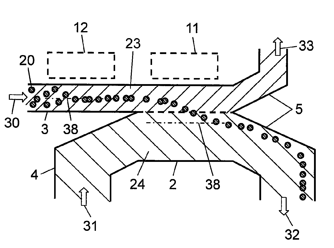
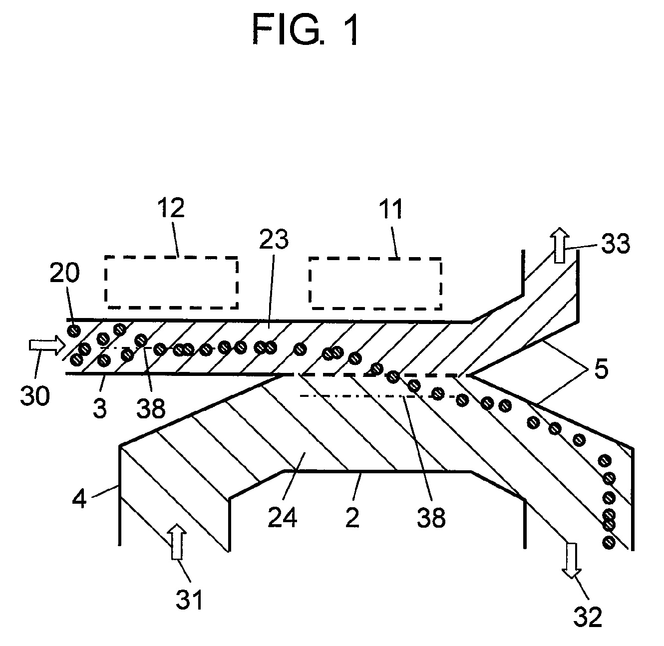
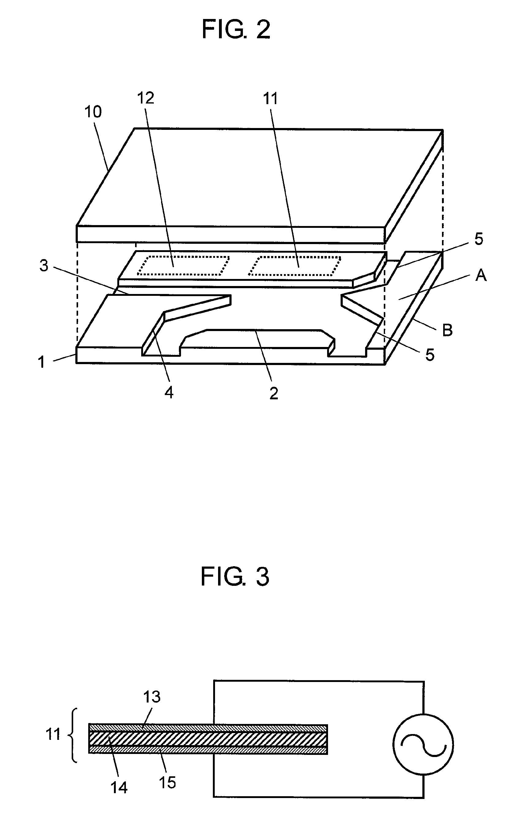
[0048]A component separating device and a component separating method with the device in accordance with Exemplary Embodiment 1 of the present invention will be described below with reference to the accompanying drawings. FIG. 1 is a plan view of the component separating device in accordance with Embodiment 1 of the invention. FIG. 2 is a perspective exploded view of the component separating device shown in FIG. 1. FIG. 3 is a sectional view of acoustic wave generator 11. The same components are denoted by the same reference numerals.

[0049]As shown in FIG. 2, reference numerals 1 denotes a substrate made of silicon. Flow channel 2 having a predetermined width and a predetermined depth is formed in surface A (an upper surface) of substrate 1. Acoustic wave generator 11 which generates an acoustic wave in flow channel 2 is provided on surface B (a lower surface) of substrate 1. This structure is provides high productivity due to acoustic wave generator 11 provided on the lower surface...

exemplary embodiment 2

[0082]A component separating device in accordance with Exemplary Embodiment 2 of the present invention will be described below with reference to the accompanying drawings. FIG. 7 is a plan view of the component separating device in accordance with Embodiment 2.

[0083]As shown in FIG. 7, branching section 7 is provided at a region in first inlet channel 3 having solid particles 20 distributed at a high density. Inlet aperture 8 and second inlet channel 4 are provided between first inlet channels 3 branched at branching section 7. Second inlet channel 4 and branched first inlet channels 3 are connect with flow channel 2. This structure allows first solution 23 introduced from first inlet channel 3 to flow together with second solution 24 introduced from second inlet channel 4 in flow channel 2 such that second solution 24 contacts the region in first solution having solid particles 20 distributed at the higher density.

[0084]This structure allows second solution 24 to join in a vicinity...

exemplary embodiment 3

[0086]A component separating device and a separating method with the device in accordance with Exemplary Embodiment 2 of the present invention will be described below with reference to the accompanying drawings. FIG. 8 is a plan view of the component separating device in accordance with Embodiment 3. FIG. 9 is an exploded perspective view of the device.

[0087]As shown in FIGS. 8 and 9, reference numeral 1 denotes a substrate made from silicon. Flow channel 2 having a predetermined width and a predetermined depth is formed in a first surface of substrate 1. Acoustic wave generator 11 which generates an acoustic wave in flow channel 2 is formed on the other surface of substrate 1. This structure provides the device with high productivity. Since sealing cover 10 is provided on the first surface, the first surface is flat preferably. Since acoustic wave generator 11 is formed on the other surface by a thin-forming film process, generator 11 is formed preferably on the other surface which...


PUM

PropertyMeasurementUnit
densityaaaaaaaaaa
inner diameteraaaaaaaaaa
outer diameteraaaaaaaaaa

Abstract

A component separating device includes a flow channel, an acoustic wave generator for generating an acoustic wave in the flow channel, a first inlet channel for introducing a fist solution containing solid particles into the flow channel, a second inlet channel for introducing a second solution, and outlet channels for discharging a solution from the flow channel. A density grade generator is provided at the first inlet channel for forming a density grade of the solid particles. This component separating device extracts the solid particles into a high-purity solution at a high collecting rate.

Description

[0001]This Application is a U.S. National Phase Application of PCT International Application PCT / JP2008 / 001199.TECHNICAL FIELD[0002]The present invention relates to a component separating device which extracts and separates solid particles from mixture solution, such as cell culture, blood, or latex, containing the solid particles and liquid.BACKGROUND ART[0003]Cells generate gene or protein, and controls biogenic activities, such as controlling over metabolic product, immunity system, proliferating differentiation. Research on or analysis of the cells is thus ever progressing not only for clearing up the mechanism of biological reaction but also for advancing the medical diagnosis.[0004]Cells preserved in a culture solution are often extracted into a test solution for analyzing the cells with a centrifugal separator or a pipette. However, this method with those devices is a time-consuming job, and the cells may brake during the centrifugal separation, so that precious cells and an ...

Claims


Application Information

Patent Timeline
Patent Type & Authority Patents(United States)
IPC IPC(8): B01D21/28
CPCB01D21/283B01L3/502753B01L3/502761B01L2400/0436B01L2200/0652B01L2300/0816B01L2200/0636
Inventor TAKAHASHI, MAKOTONAKATANI, MASAYAHIRAOKA, SOICHIROUSHIO, HIROSHIOSHIMA, AKIYOSHI
Owner PANASONIC CORP
Why Eureka
Try Eureka