Optical arrangement comprising emitters and detectors on a common substrate

a technology of optical arrangement and emitter, applied in the field of optical arrangement, can solve the problems of increasing the difficulty of taking into account their relevance or respective importance, huge time effort also required for the detection and evaluation of information, and the rare use of passive acting systems, etc., and achieves the effect of harmonising very easily with the respective application

Active Publication Date: 2012-09-25
FRAUNHOFER GESELLSCHAFT ZUR FOERDERUNG DER ANGEWANDTEN FORSCHUNG EV
View PDF20 Cites 36 Cited by
  • Summary
  • Abstract
  • Description
  • Claims
  • Application Information

AI Technical Summary

Benefits of technology

[0024]An optical arrangement in accordance with the invention can be provided with a cover transparent to electromagnetic radiation at the side of the arrangement from which radiation can be emitted and via which incident radiation can be detected. Such a cover can also have an optical effect in addition to a protective function. For this purpose, optical structural elements can be provided on a cover and can be arranged with respect to emitting and / or detecting elements. The optical structural elements can achieve a focusing of the radiation or also a beam expansion (enlarging of the divergence).
[0025]A larger area can thus be illuminated, for example, image signals of a larger area can be detected with a different depth of field or optical information can be displayed in enlarged form. An optimization of the required size of an arrangement in accordance with the invention for an envisaged application can also thus be carried out in that, for example, the surface portion for detecting elements on a substrate can be kept smaller when the incident radiation is focused in the direction of detecting elements.
[0026]The emitting and the detecting elements are connected to an electronic evaluation and control unit. The actually different functions of the elements can thus be used in combination with one another, which can be harmonized very easily with the respective application.

Problems solved by technology

In this context, it is becoming more and more difficult to take account of their relevance or their respective importance, in particular when decisions have to be taken in a short time.
However, a huge time effort is also required for the detection and also evaluation of the information.
Passively acting systems tend to be rare in use and are also limited in their effect.
Too large a time delay also frequently occurs due to the required effort for the evaluation of information.

Method used


Image

  • Optical arrangement comprising emitters and detectors on a common substrate
  • Optical arrangement comprising emitters and detectors on a common substrate
  • Optical arrangement comprising emitters and detectors on a common substrate

Examples


Embodiment Construction

)

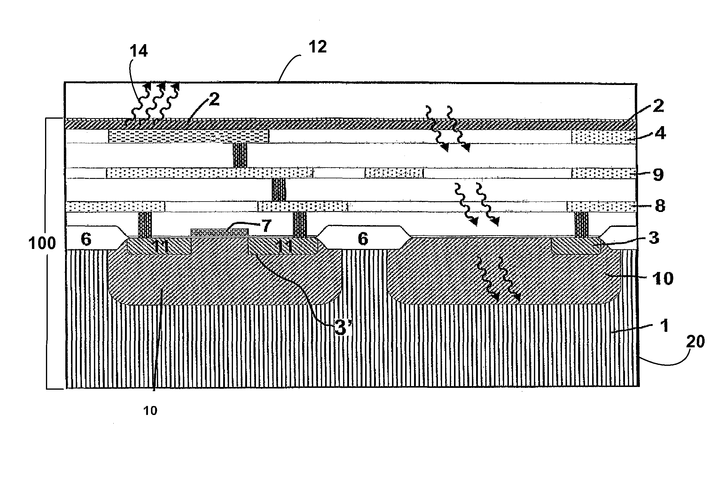
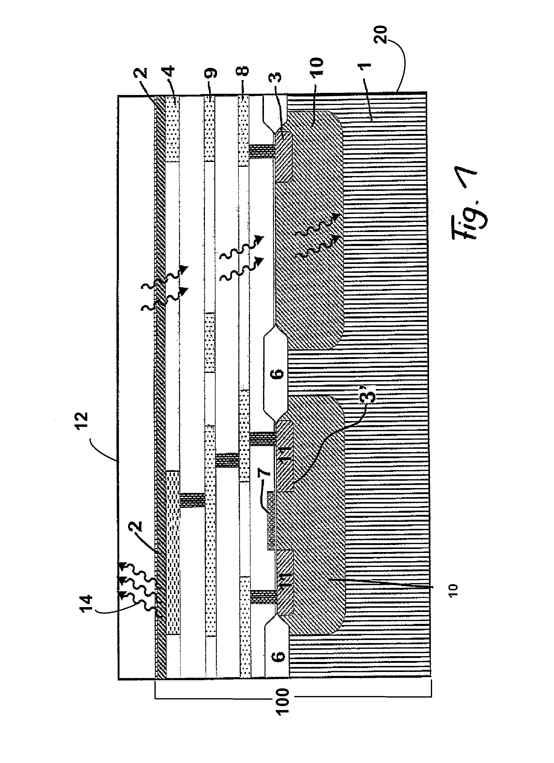
[0041]A possible design of an example of an arrangement 100 in accordance with the invention can be seen from the schematic representation of FIG. 1. In this connection, a design with organic light emitting diodes 2, in an embodiment known per se, can be present on a substrate 1 made of silicon as elements emitting electromagnetic radiation. Metallic layers in a structured form are moreover configured which form electrical conductors and electronic components. A transistor 3′ is thus associated with an organic light emitting diode 2. In one aspect, the arrangement 100 is accommodated in a housing 20 with at least a transparent portion 12 on which electromagnetic radiation 14 emitted by the elements 2 is imaged. In a further aspect, housing 20 is operable to be placed onto at least one eye of a living being / creature so that image information that is imaged in the housing 20 by projection can also be visually detected by the living creature.

[0042]In the example shown in FIG. 1, a pho...


PUM


Abstract

The invention relates to optical arrangements which can be provided, preferably also in miniaturized form, for the most varied applications. They can be used in many sectors of life and also commercially, and indeed whenever information should be presented visually and / or optical information should be recognized and taken into account. It is the object of the invention to provide optical arrangements with which different optical information can be utilized in more complex form together in one arrangement. The optical arrangement in accordance with the invention is configured such that elements both emitting and detecting electromagnetic radiation are arranged on a common substrate or are configured thereat. A plurality of these elements are preferably present together in each case. It can, however, also be sufficient for specific applications to provide in each case an emitting or a detecting element with a plurality of the respective other elements.

Description

BACKGROUND OF THE INVENTION[0001]The invention relates to optical arrangements which can be provided, preferably also in miniaturized form, for the most varied applications. They can be used in many sectors of life and also commercially, and indeed whenever information should be presented visually and / or optical information should be recognized and taken into account.[0002]For example, “smart” displays can thus be made available which are particularly suitable for interactive uses.[0003]The flood of the most varied information systems and environmental influences provides a correspondingly increasing number of demanded information, but also of information which has not been demanded, which has to be or should be processed or taken into account by humans. In this context, it is becoming more and more difficult to take account of their relevance or their respective importance, in particular when decisions have to be taken in a short time. However, a huge time effort is also required f...

Claims


Application Information

Patent Timeline
Patent Type & Authority Patents(United States)
IPC IPC(8): G01J1/44H01J40/14H03F3/08
CPCH01L31/173H01L27/3269H01L27/3227H01L27/14678H10K59/60H10K59/13
Inventor VOGEL, UWEAMELUNG, JORGKREYE, DANIEL
Owner FRAUNHOFER GESELLSCHAFT ZUR FOERDERUNG DER ANGEWANDTEN FORSCHUNG EV
Why Eureka
Try Eureka