Thermal control unit for semiconductor testing

a control unit and semiconductor technology, applied in the field of semiconductor control units for semiconductor testing, can solve the problems of more difficult control of the temperature of the semiconductor device during burn-in, semiconductor device over 100 watt generation, and even higher electrical consumption of the latest semiconductor device, so as to reduce the rate of heat transfer from the semiconductor device to the heat pipe, and reduce the rate at which the heat pipe conducts heat

Inactive Publication Date: 2012-09-25
KES SYST & SERVICE 1993 PTE
View PDF11 Cites 13 Cited by
  • Summary
  • Abstract
  • Description
  • Claims
  • Application Information

AI Technical Summary

Benefits of technology

[0011]The thermal control unit (TCU) described herein has integrated components that conduct heat away from the semiconductor device during the burn-in process in a controlled and adaptive manner. In one embodiment the integrated components include a liquid-containing heat transfer device commonly referred to as a heat pipe. The heat pipe is equipped with a heater that is used to control the rate at which heat is conducted away from the semiconductor device. The heater is controlled by a thermal regulator that senses the temperature of the semiconductor device under test. When the temperature of the semiconductor device is sensed to be at or above a predetermined threshold temperature, the heater is off and the heat pipe conducts heat away from the semiconductor at the maximum rate. If the temperature of the semiconductor device falls below a certain threshold, the rate of heat transfer from the semiconductor device to the heat pipe is reduced by activating the heater. In one embodiment the heater heats the surface of the heat pipe which reduces the rate at which the heat pipe conducts heat away from the semiconductor device.
[0015]In this embodiment, the heater is constructed as a jacket around the exterior wall of the heat pipe. If the controller determines that the temperature of the semiconductor device is at or below a certain threshold, and therefore the rate of cooling is to be slowed, the sensor will turn the heater on. The heater, when turned on, heats the wall of the heat pipe, and also the temperature of the liquid flowing from the cooling end of the heat pipe down to the bottom. Heating the liquid slows down the rate of heat transfer from the semiconductor device to the heat pipe. For example, the cooled condensate is reheated by the heater, causing it to again vaporize. As such the cooled liquid is not returned to the reservoir to lower the temperature of the remaining liquid. This causes the liquid in the reservoir at the end proximate the semiconductor device to cool more slowly, which slows the rate of heat transfer from the semiconductor device to the heat pipe. This in turn causes the temperature of the semiconductor device to rise until it reaches the predetermined threshold where the heater is again turned off, and heat is conducted away from the semiconductor device by the heat pipe at the maximum rate. The end of the heat pipe adjacent the semiconductor device is embedded in a jacket, which is preferably made of a material that conducts heat. In one embodiment, the heat pipe is embedded in a copper block. In other embodiments, a plurality of heat pipes are embedded in the copper block, which is placed adjacent to the semiconductor device. A sensor is interposed between the heat pipe and the semiconductor device. The sensor is positioned such that it can sense the temperature of the semiconductor device and provide an accurate determination of when the rate of heat transfer from the semiconductor device to the heat pipe needs to be changed.

Problems solved by technology

Consequently, since the power dissipation during burn-in is significantly higher than under normal operation, the extra power dissipation makes it even more difficult to control the temperature of the semiconductor device during burn-in.
The latest semiconductor devices, especially microprocessors, have even higher electrical consumption in accordance with their higher frequency of operation.
The higher electrical consumption causes the semiconductor devices to generate heat over 100 watts.
In the burn-in of these devices, the heat generated when these devices are continuously connected with electricity at constant high temperature (e.g., about 125° C.) can be catastrophic.
Unless these heat generating semiconductor devices are appropriately cooled to a controlled temperature, the burn-in testing equipment itself might be destroyed in addition to the semiconductor devices under test (DUTs).
While not capable of fine temperature control, this configuration provides greater cooling capacity than a similar configuration with no air flow control capability.

Method used


Image

  • Thermal control unit for semiconductor testing
  • Thermal control unit for semiconductor testing
  • Thermal control unit for semiconductor testing

Examples


Embodiment Construction

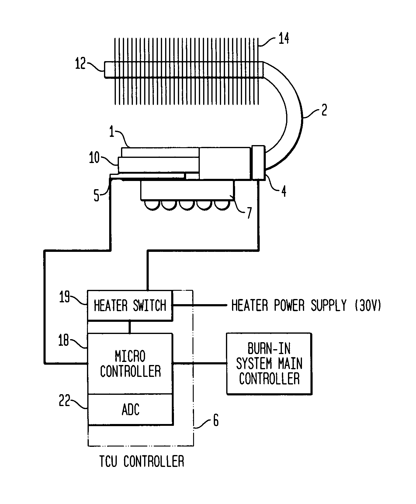
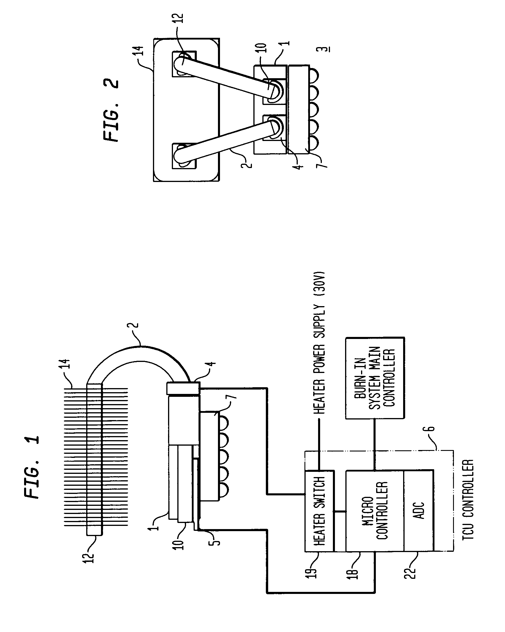
[0034]FIG. 1 is a schematic diagram of an active thermal control system for regulating the temperature of a device under test (DUT). For purposes of the example embodiment described herein, DUT is an electronic semiconductor circuit device, such as a microprocessor chip. Alternatively, DUT may be any electronic, mechanical or other device being subjected to one or more tests performed under specific temperature settings. DUT 7 is preferably held in close proximity to cooling assembly 3, which is configured to regulate the temperature of DUT 7. In the preferred embodiment, a portion of DUT 7 such as the device surface, contacts cooling assembly 3. In a practical embodiment, cooling assembly 3 is coupled to a compatible carrier (not shown). The carrier and DUT 7 are clamped together during thermal conditioning, testing, and cool down of DUT 7. In response to such clamping, DUT 7 is forced into physical contact with cooling assembly 3. Such clamping ensures that heat is effectively tra...


PUM


Abstract

A thermal control unit with a heat pipe that conducts heat away from a device under test during burn-in. The heat pipe has a heater that allows control of the rate at which heat is transferred from the DUT to the heat pipe. A sensor and controller are provided to control the heat in response to the measured temperature of the DUT. The sensor and controller control the heater to maintain the surface temperature of the DUT within a specified range.

Description

CROSS REFERENCE TO RELATED APPLICATIONS[0001]This application claims the benefit of the filing date of U.S. Provisional Patent Application No. 61 / 011,563 filed Jan. 18, 2008, the disclosure of which is hereby incorporated herein by reference.FIELD OF THE INVENTION[0002]The present invention is directed to an apparatus and method for controlling the temperature of an integrated circuit during the test and burn-in process.BACKGROUND OF THE INVENTION[0003]Semiconductor devices, i.e., integrated circuits, are tested after packaging to identify those devices that are likely to fail shortly after being put into use. This test is described as a burn-in test. The burn-in test thermally and electrically stresses the semiconductor devices to accelerate the failure of those devices that would otherwise fail early on. This ensures that the devices sold to customers are more reliable.[0004]The burn-in test can take many hours to perform and the temperature of the semiconductor devices is held in...

Claims


Application Information

Patent Timeline
Patent Type & Authority Patents(United States)
IPC IPC(8): G01R31/00
CPCG01R31/2875G05D23/1904G01R31/2874
Inventor SAKAUE, NAOTOKONG, FOOK SENG
Owner KES SYST & SERVICE 1993 PTE
Why Eureka
Try Eureka