Electric winding body and transformer having forced cooling

Active Publication Date: 2012-09-25
SIEMENS ENERGY GLOBAL GMBH & CO KG
View PDF8 Cites 2 Cited by
  • Summary
  • Abstract
  • Description
  • Claims
  • Application Information

AI Technical Summary

Benefits of technology

[0023]The object is likewise achieved by a transformer having at least one core which can be magnetized, having a yoke and having at least two limbs, as well as at least two electrical winding bodies each having an electrically conductive winding and insulation surrounding the respective winding, wherein the surrounding insulation surrounds the respective winding and in each case forms a mechanically robust winding body, and an electrical winding body is arranged on one limb. The invention provides that at least one separating element is arranged between two electrical winding bodies, wherein the separating element comprises at least two side elements, which can be fixed to one another at the rear. The capability to attach the side elements such that they can be fixed to one another at the rear allows the separating element to be fitted easily and retrospectively between the electrical winding bodies. The separating elements can advantageously be fitted with the core, in particular the yoke, and/or directly to at least one winding body.
[0024]In one advantageous refinement of the transformer, the side elements of the separating element can be fixed by means of at least one attachment element at the rear wall, wherein the force effect of t

Problems solved by technology

In fact, in the prior art, the different temperature and flow conditions on the upper face of the transformer

Method used


Image

  • Electric winding body and transformer having forced cooling
  • Electric winding body and transformer having forced cooling
  • Electric winding body and transformer having forced cooling

Examples


Embodiment Construction

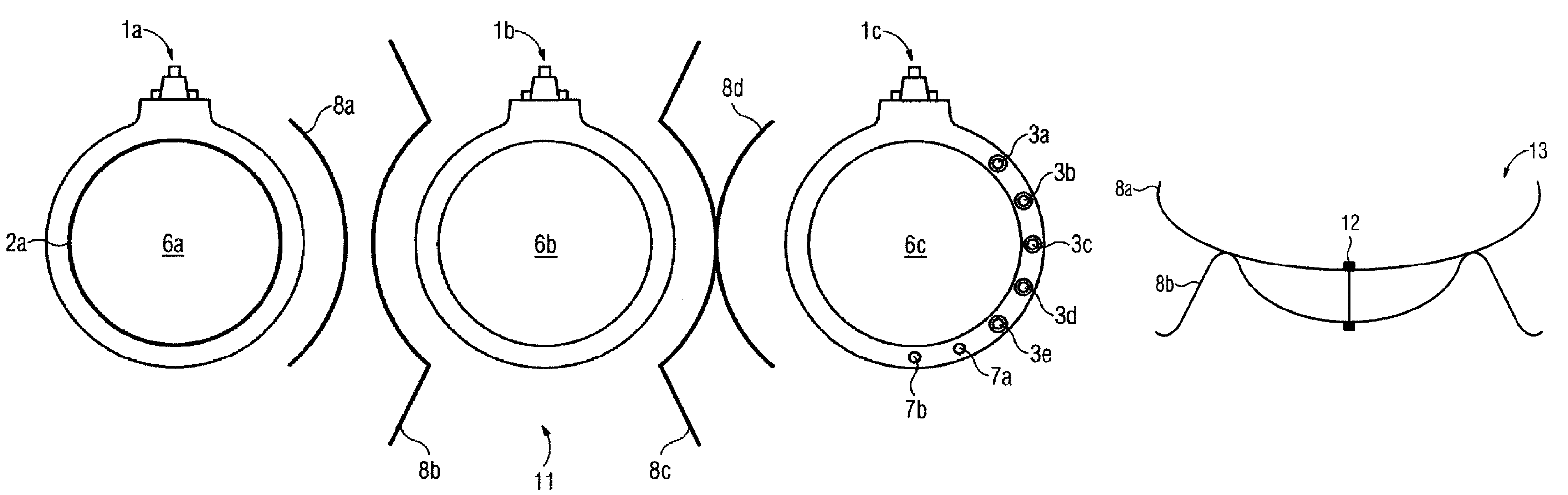
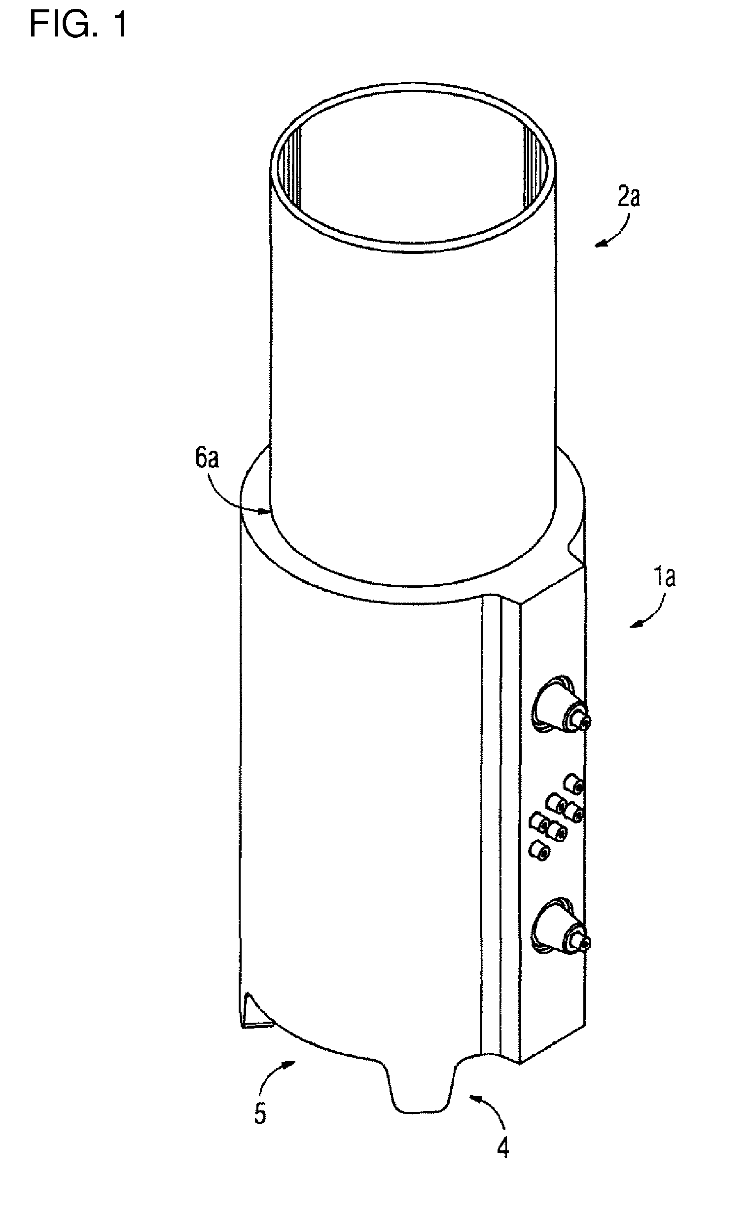
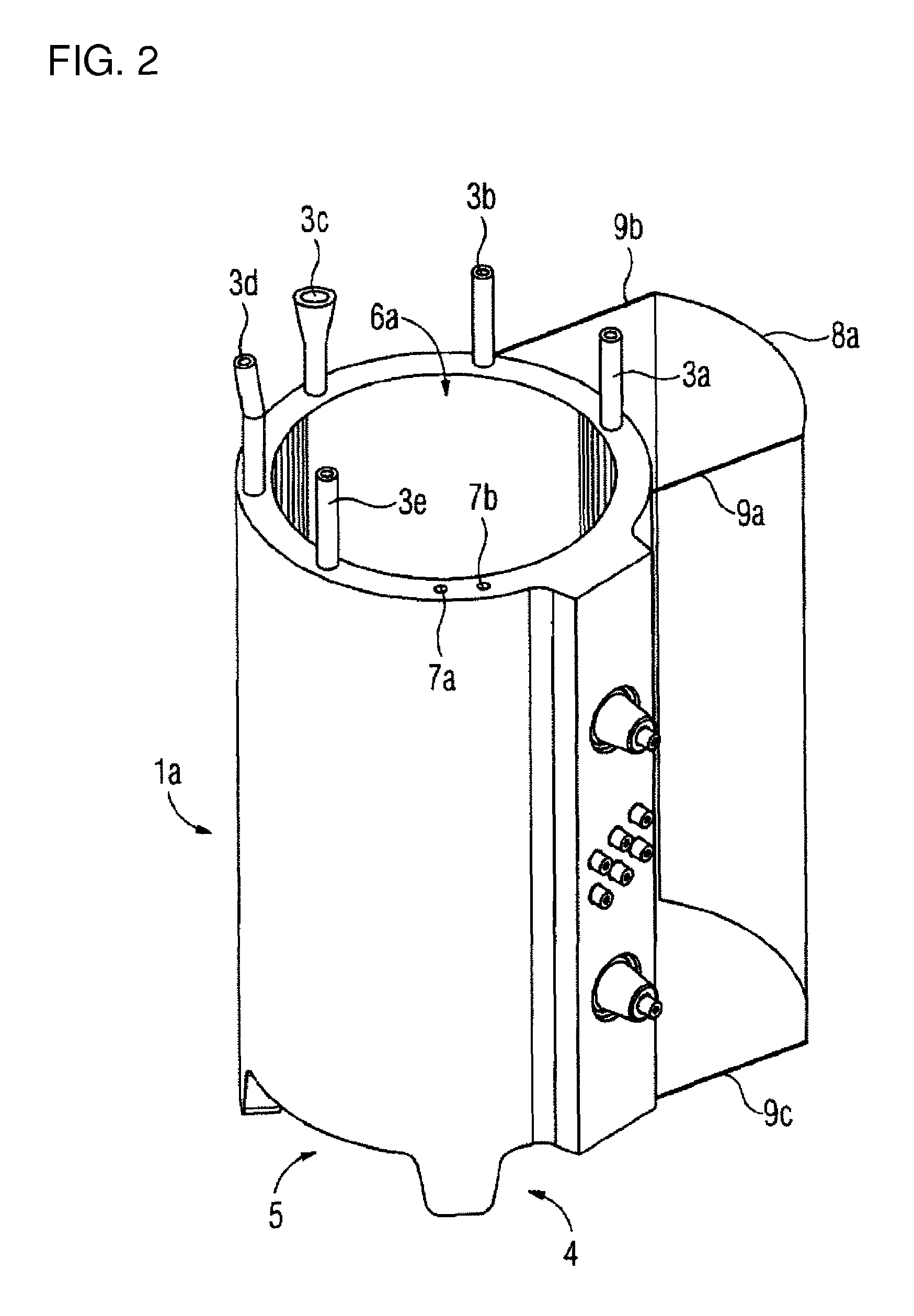
[0038]FIG. 1 shows a perspective view of the electrical winding body 1a with feet 4 which form a gap 5 under the electrical winding body 1a. Air can flow from below into the continuous channels 10a, 10b, 10c (10a is not illustrated) through the gap 5. A core which can be magnetized can be inserted into the continuous center channel 10a (not illustrated) in the electrical winding body 1a, such that the electrical winding body 1a can be used as part of a transformer. An extension element 2a can be inserted into the continuous channel 10a and, for example, is in the form of a cylinder. The cooling medium, in particular air, can be carried away from the electrical winding body 1a through the upper opening of the cylinder. The air passes via the gap 5 into one of the continuous channels 10a to 10c, and flows out of the opening of the extension element 2a, by virtue of the chimney effect. The present invention greatly reduces and impedes any influence on the flow and convection conditions...


PUM


Abstract

An electrical winding body includes an electrically conductive winding and an insulation surrounding the winding. The surrounding insulation surrounds the entire winding and forms a mechanically stable winding body. At least one continuous channel having an opening in the electrical winding body is disposed inside the winding body. An extension element is placed in the openings of the continuous channels to elongate the channels beyond the dimensions of the electrical winding body, thus providing for improved cooling. Side elements are additionally attached on the outer wall of the electrical winding body to create an intermediate space which forms a new cooling channel that produces an additional cooling effect due to an air current created by the chimney effect.

Description

BACKGROUND OF THE INVENTIONField of the Invention[0001]The invention relates to an electrical winding body having an electrically conductive winding and insulation surrounding the winding, wherein the surrounding insulation surrounds the entire winding and forms a mechanically robust winding body, and at least one continuous channel having an opening in the electrical winding body is arranged within the electrical winding body. The invention also relates to a transformer having an electrical winding body according to the invention. The electrical winding bodies are part of a transformer.[0002]The thermal load on a transformer, in particular a cast-resin transformer, has a considerable influence on the life of the transformer. Adequate cooling of the windings is therefore essential in particular for air-cooled transformers, such as cast-resin transformers.[0003]By way of example, EP 0092204 A2 describes an induction coil wherein, according to the invention there, cooling channels are...

Claims


Application Information

Patent Timeline
IPC IPC(8): H01F27/02
CPCH01F27/085H01F27/2876H01F27/327H01F27/324H01F27/322
Inventor HANOV, RUDOLFSORG, FRITZ
Owner SIEMENS ENERGY GLOBAL GMBH & CO KG
Why Eureka
Try Eureka