Vehicle display apparatus

a technology of liquid crystal display and display device, which is applied in the direction of static indicating device, simultaneous indication of multiple variables, instruments, etc., can solve the problems of image brightness that is not likely to achieve the original purpose, and achieves sufficient brightness and ease of viewing the meter imag

Active Publication Date: 2012-09-25
DENSO CORP
View PDF31 Cites 5 Cited by
  • Summary
  • Abstract
  • Description
  • Claims
  • Application Information

AI Technical Summary

Benefits of technology

[0007]The display apparatus of the present invention controls the meter display gradation ratio and the warning display gradation ratio respectively controlling meter display pixels and warning display pixels according to the input adjustment value that comes from occupants of the vehicle. The brightness of the meter image and the warning image is adjusted so that the brightness of the warning image stands out from the brightness of the meter image by adjusting the warning display gradation ratio to be greater than the meter display gradation ratio. Thus, the ease of viewing of the meter image is improved by sufficiently suppressing the brightness according to the input adjustment value, and, at the same time, the warning image is displayed with sufficient brightness maintained for achieving the display purpose of the image, that is, for calling the occupant's attention at the suppressed brightness. As a result, each of the meter image and the warning image respectively having different display purposes is appropriately displayed.

Problems solved by technology

However, an outside image that is generated by capturing outside world for calling attention for the situation outside of the vehicle as well as a warning image that warns abnormality of the vehicle or the images having similar purposes, that is, the images that require certain brightness, are not likely to achieve their original purposes.

Method used


Image

  • Vehicle display apparatus
  • Vehicle display apparatus
  • Vehicle display apparatus

Examples


first embodiment

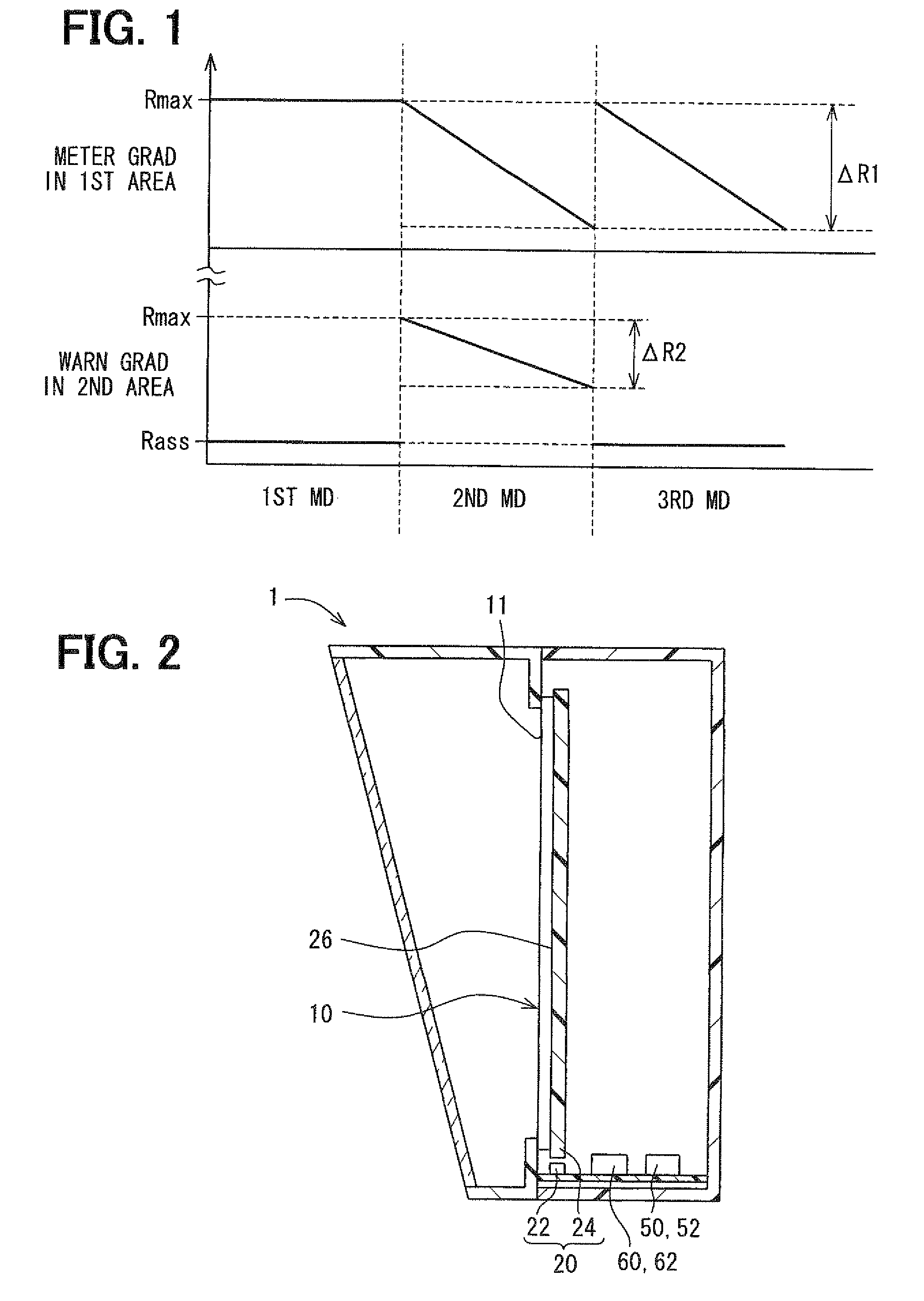
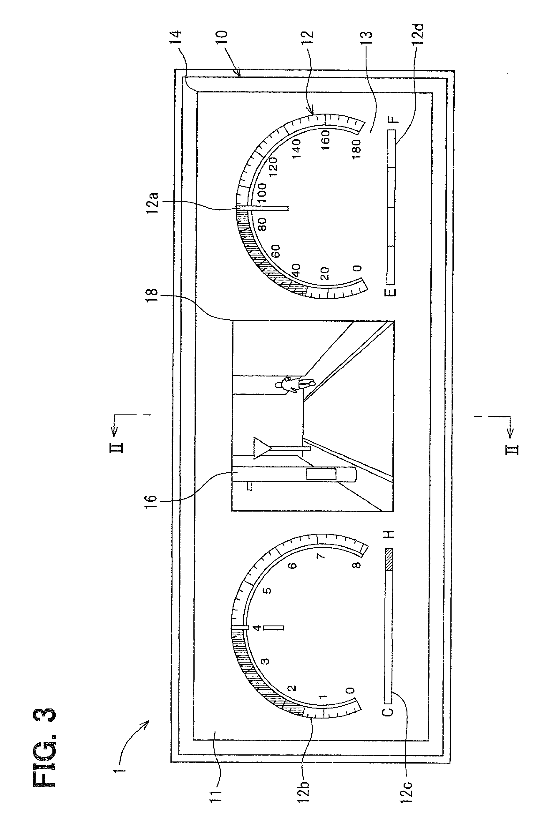
[0054]FIGS. 2, 3 show a cross-sectional view and a front view of a vehicle display unit 1 in the first embodiment of the present invention, and FIG. 4 shows electric circuit configuration of the unit 1.

[0055]The vehicle display unit 1 serves as a combination meter as shown in FIGS. 2 to 4, and includes a liquid crystal panel 10, a backlight 20, an input unit 30, an imaging unit 40, a drawing unit 50 and a main control unit 60.

[0056]The liquid crystal panel 10 is a TFT transparent liquid crystal panel, and the panel 10 is installed in front of the driver's seat with a screen 11 facing to the driver's seat side of the vehicle. The liquid crystal panel 10 is a dot matrix type panel having plural pixels arranged in the shape of a matrix, and realizes a full color image display on the screen 11 by driving each of the pixels. As for the pixel of the liquid crystal panel 10, three subpixels of R, G, B respectively equipped with a red / green / blue filter are disposed. The drawing unit 50 that...

second embodiment

[0106]The second embodiment of the present invention is the modification of the first embodiment. In addition, in the according to description, the focus is mainly put on the explanation of the difference of the second embodiment from the first embodiment on the first embodiment.

[0107]A backlight 120 uses two sets of lighting, that is, a first light emitting diode 122 and a first diffusion board 124a which emit light transparently at both sides of the second pixel area 18 to light up the first pixel area 14 of the liquid crystal panel 10 as a first light source 128a in the vehicle display unit 100 of the second embodiment as shown in FIG. 10. In addition, the backlight 120 uses two sets of lighting, that is, a second light emitting diode 122b and a second diffusion board 124b which emit light transparently to light up the second pixel area 18 at the substantially central part of the liquid crystal panel 10 as a second light source 128b.

[0108]The light emitting diodes 122a, 122b are...

third embodiment

[0135]The third embodiment of the present invention is the modification of the first embodiment. In addition, in the according to, the focus of the description is mainly put on the difference of the third embodiment from the first embodiment.

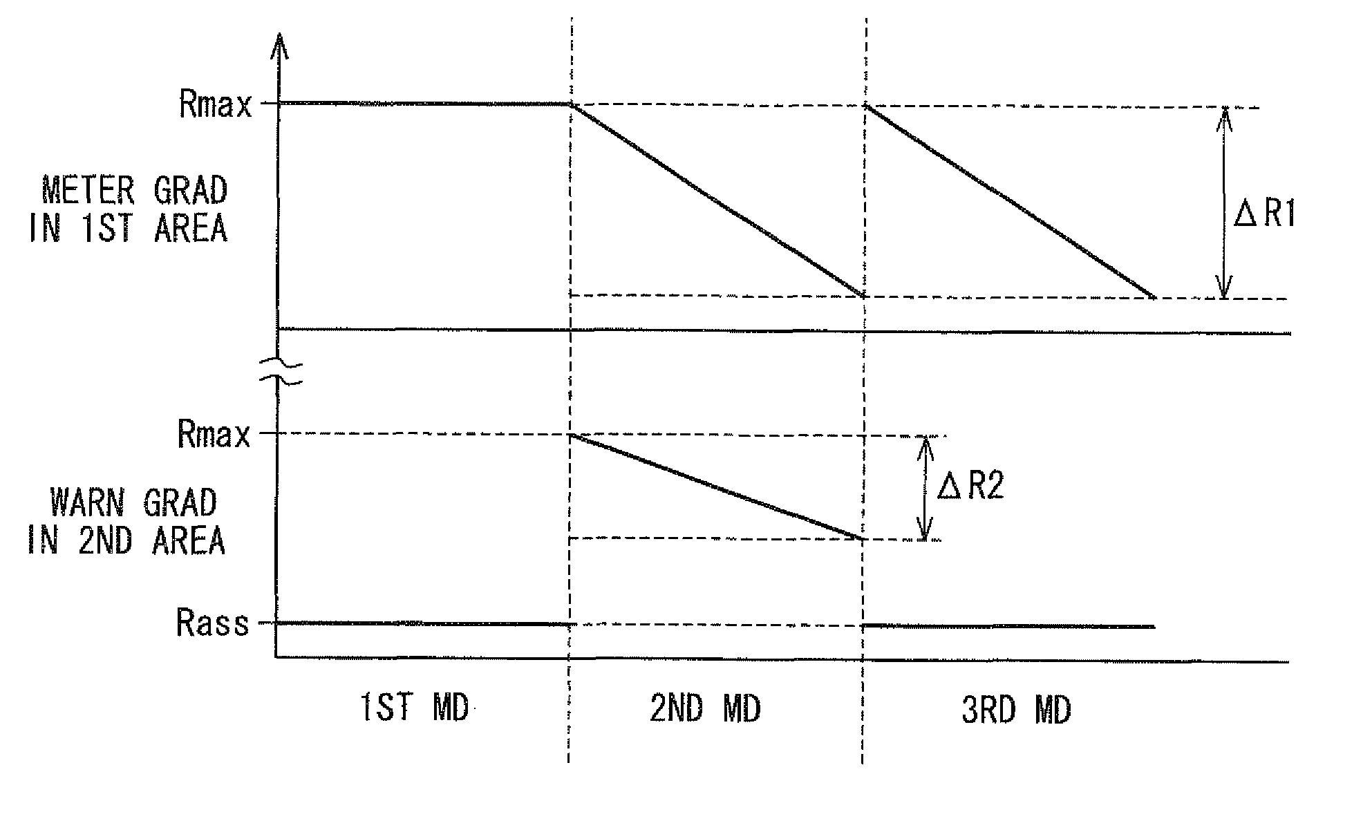
[0136]In the third embodiment, the first correlation information and the second correlation information are defined respectively in a manner that the meter display gradation ratio of the first pixel area 14 and the warning display gradation ratio of the second pixel area 18 linearly decrease, in proportion to the increasing change of the input adjustment value, from respectively different standard ratios R1 and R2 with the linear decrease rate of the latter being smaller than the former as shown in FIG. 16. In this case, while the standard ratio R2 of the warning display gradation ratio in the second pixel area 18 is set to the maximum ratio of Rmax, the standard ratio R1 of the meter display gradation ratio in the first pixel area 14 is set to ...


PUM


Abstract

A display apparatus for use in a vehicle has a liquid crystal display panel, and the panel includes a first pixel area for displaying a meter image that represents vehicle condition values, and a second pixel area for displaying an outside image that calls attention of occupants as a warning image. Further, an input unit of the apparatus receives inputs of adjustment value from occupants of the vehicle for adjusting brightness of the meter image and the outside image. A main control unit and a drawing unit of the apparatus cooperatively serve as a controller of the apparatus by changing gradation ratio of the first and second pixel areas so that the gradation ratio of the second pixel area becomes greater than the gradation ratio of the first pixel area according to the input of the adjustment value.

Description

CROSS REFERENCE TO RELATED APPLICATION[0001]The present application is based on and claims the benefit of priority of Japanese Patent Applications No. 2007-103130 filed on Apr. 10, 2007, and No. 2007-279361 filed on Oct. 26, 2007, the disclosures of which are incorporated herein by reference.FIELD OF THE INVENTION[0002]The present disclosure generally relates to a liquid crystal display apparatus for use in a vehicle.BACKGROUND INFORMATION[0003]Conventionally, a liquid crystal display panel illuminated by a lighting device is used for displaying images in a vehicle. The liquid crystal display of the conventional apparatus has a control function for controlling a gradation value of pixel in the liquid crystal display panel, or for controlling light emission brightness of the lighting device as disclosed, for example, in Japanese patent documents JP-A-2004-284508, JP-A-2006-258783 or the like. The liquid crystal display panel in the conventional apparatus decreases the gradation value...

Claims


Application Information

Patent Timeline
Patent Type & Authority Patents(United States)
IPC IPC(8): G09G3/36
CPCB60K35/00G01D7/02G01P1/08G07C5/0891G09G3/3406G09G3/342B60K2350/1072B60K2350/2013G09G3/3611G09G2300/026G09G2320/0626G09G2320/0673G09G2320/0686B60K2370/155B60K2370/21G01D2207/30
Inventor KATO, MIKISHIBATA, YUKIHIDEMIYAGAKI, TOMOYUKI
Owner DENSO CORP
Why Eureka
Try Eureka