System and methods for creating a three-dimensional view of a two-dimensional map

a two-dimensional map and three-dimensional image technology, applied in the field of computer systems, can solve the problems of difficult to view two-dimensional maps next to each other, difficult to compare relative sizes or distances, projections that may not handle adjacent maps correctly, etc., to facilitate fly-by and/or fly-through simulations

Active Publication Date: 2012-09-25
ADOBE INC
View PDF24 Cites 73 Cited by
  • Summary
  • Abstract
  • Description
  • Claims
  • Application Information

AI Technical Summary

Benefits of technology

[0010]Various geospatial data formats may be supported, in different embodiments. In some embodiments, a simple form of geospatial reference may be provided within the output 3D data, such that a measurement function may display latitude and/or longitude coordinates for a point position and may compute and/or display a distance between two points in the geospatially aware 3D data. In one example, a 3D view may be created from a 2D map stored in a GeoTIFF image (e.g., one formatted in accordance with GeoTiff Revision 1.8.2, 10 Nov. 1995, or any other compatible version) having additional embedded geospatial information. GeoTIFF is a metadata standard that allows embedding of geo-referencing information in a file formatted using the Tagged Image File Format (TIFF). In this example, the GeoTIFF image may include a JPEG image of a map, along with embedded location information and/or and data indicating the extent of the image on the Earth. The system and methods described herein may in some embodiments be used to convert the image to a 2D document in a portable document format (PDF) that includes the geospatial inform

Problems solved by technology

Two-dimensional projection of graphical images, such as maps, tends to distort some data, making it harder to compare relative sizes or distances.
In addition, some projections may not handle adjacent maps correctly, a

Method used


Image

  • System and methods for creating a three-dimensional view of a two-dimensional map
  • System and methods for creating a three-dimensional view of a two-dimensional map
  • System and methods for creating a three-dimensional view of a two-dimensional map

Examples


Embodiment Construction

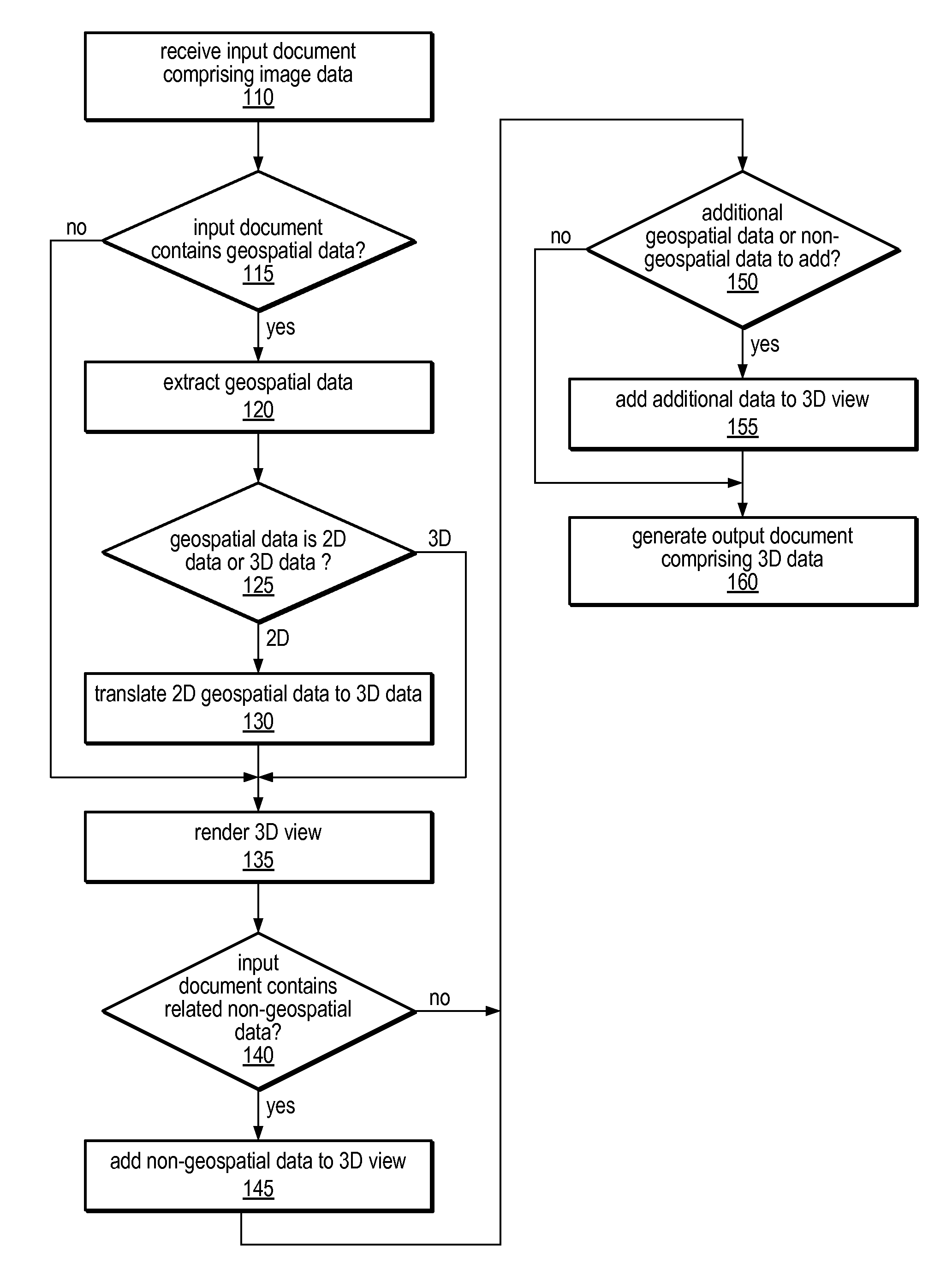
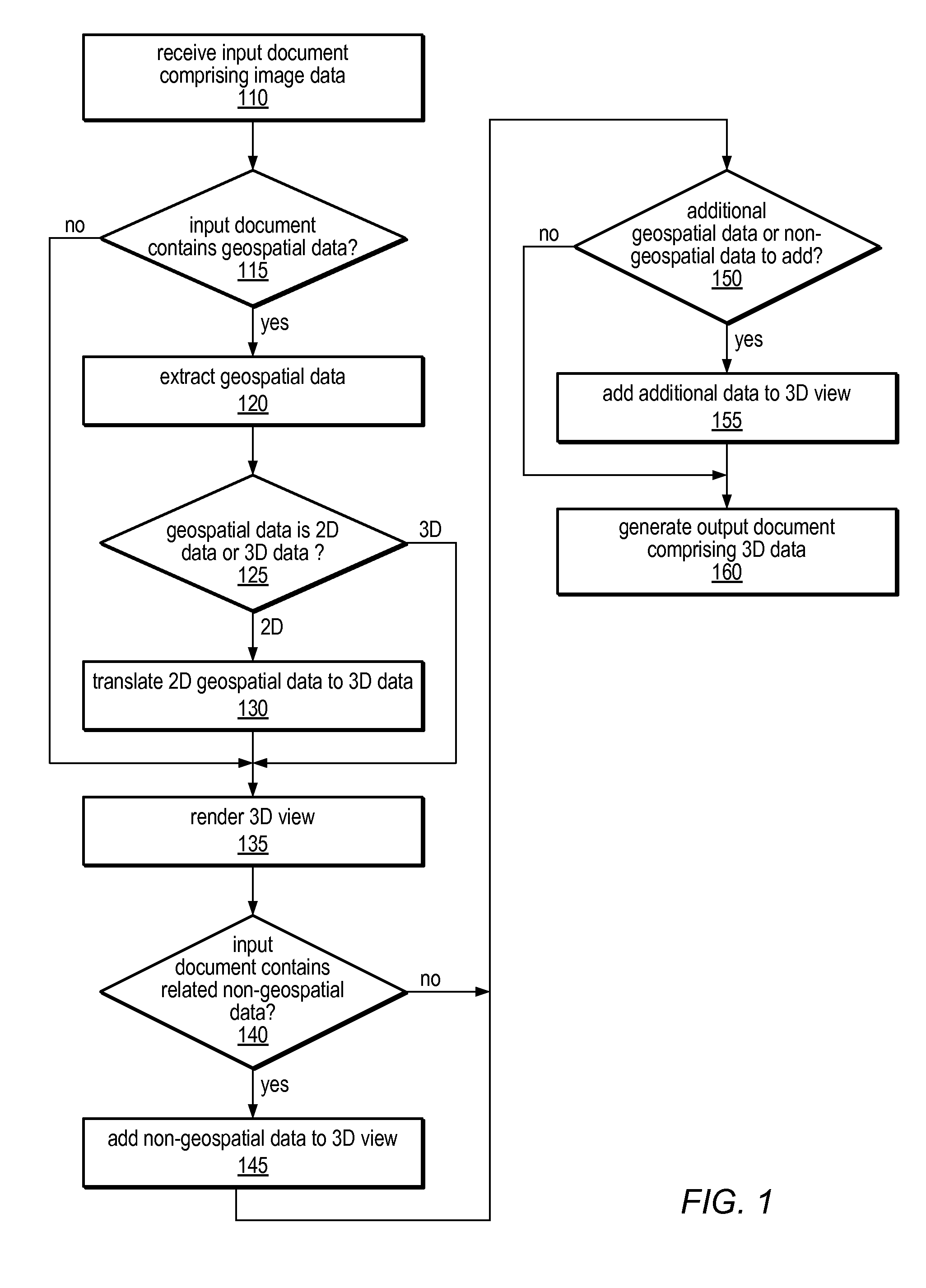
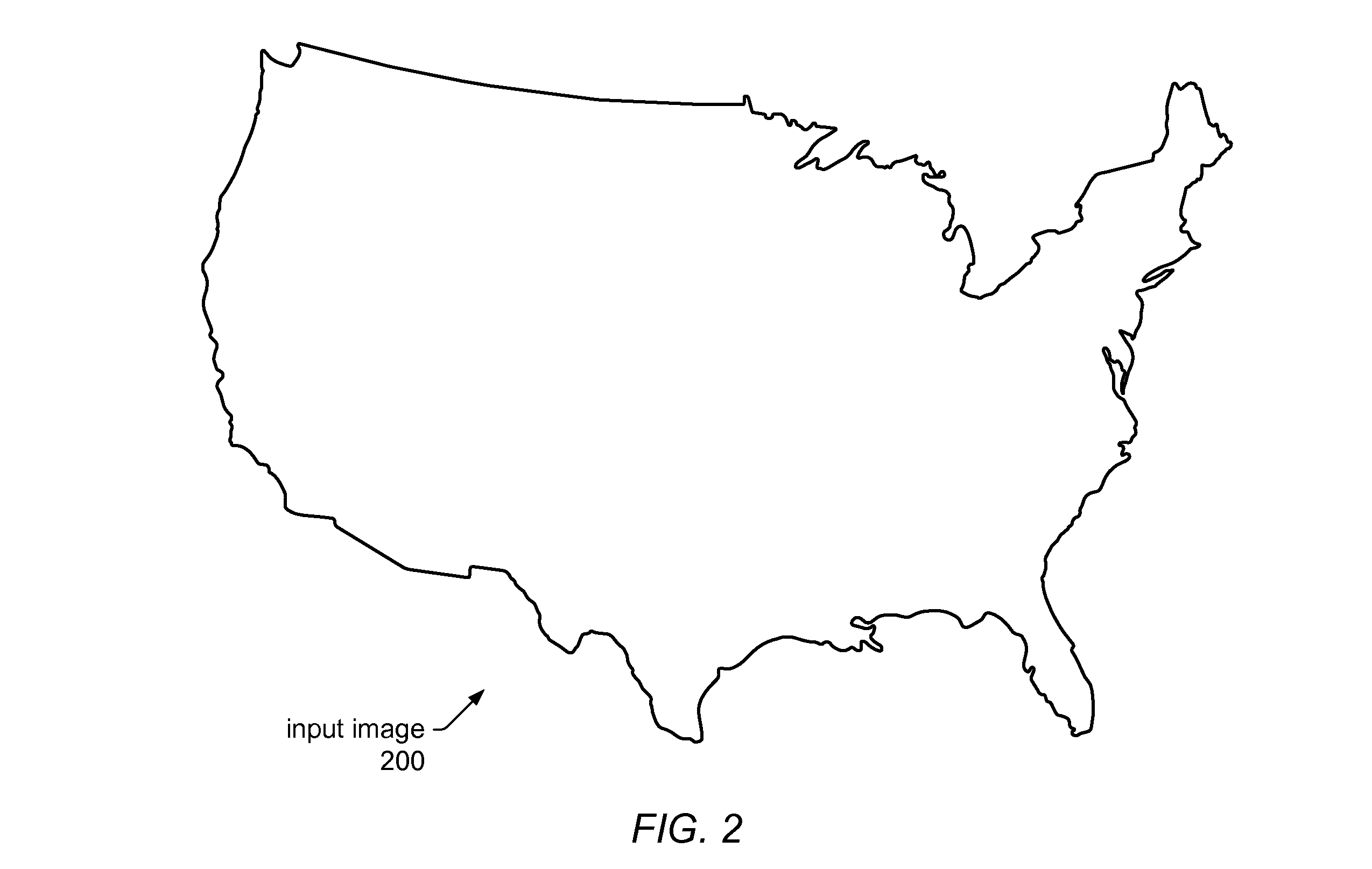
[0024]Various embodiments of systems and methods for rendering three-dimensional (3D) views of a two-dimensional (2D) image (e.g., a map) are disclosed. In some embodiments, the system may receive a document containing 2D image data (e.g., data representing a flat map) and may convert the image into a 3D rendering of the image as projected upon the surface of the Earth (or another celestial body). In other words, a 3D translator, as described herein, may take a document in a portable document format (e.g., PDF) as its input, and for each page in the document, may determine whether a geospatial feature (e.g., a map) is included on the page. If so, the document-based 3D translator may draw each element of the page (or each element of a map included in the page) as projected on the Earth. In some embodiments, the input document may include the location, the extent of the map area on Earth, and / or the projection of the map, embedded as geospatial information in the document. In such emb...


PUM


Abstract

Systems, methods, and computer-readable storage media for generating 3D views of 2D images are disclosed. Image data representing a 2D map may be included in an input document in a portable document format, along with embedded geospatial information related to the map. A document-based 3D translator may extract image data and other information from the input document and may translate the image into a map projected on a 3D model of the Earth's surface, using embedded location and/or extent information. Additional information may be projected on the map image or displayed as a height, texture, or color, or as separate, anchored, or floating text. Image data representing the 3D view may be output to the same or a different document file. The methods may be implemented in a system comprising a CPU and/or a GPU, and/or as program instructions, stored on computer-readable media, executable by the CPU and/or GPU.

Description

BACKGROUND[0001]1. Field of the Invention[0002]The present invention is directed to computer systems; and more particularly, it is directed to the compositing and rendering of three-dimensional images from two-dimensional maps using computer systems.[0003]2. Description of the Related Art[0004]As the power and complexity of personal computer systems increase, graphics operations are increasingly being performed on these systems, often making use of dedicated graphics rendering devices referred to as graphics processing units (GPUs). As used herein, the terms “graphics processing unit” and “graphics processor” are used interchangeably. Although GPUs vary in their capabilities, they may typically be used to perform such tasks as rendering of two-dimensional (2D) graphical data, rendering of three-dimensional (3D) graphical data, accelerated rendering of graphical user interface (GUI) display elements, and digital video playback. A GPU may include various built-in and configurable stru...

Claims


Application Information

Patent Timeline
IPC IPC(8): G06T15/00G06F3/00
CPCG06T15/04G06T17/05
Inventor REES, DAVID B T
Owner ADOBE INC
Why Eureka
Try Eureka