Mount adapter device utilizing a push system

a technology of mounting adapter and push system, which is applied in the direction of sighting devices, cart extractors, weapons, etc., can solve the problems of insufficient clamping force, inability to meet user demands, and current devices that cannot be mounted to the rails, etc., to achieve fast locking or unloading from the rails, maximum holding strength, and uniform tension

Active Publication Date: 2012-10-02
SAMAK ENTERPRISES
View PDF20 Cites 33 Cited by
  • Summary
  • Abstract
  • Description
  • Claims
  • Application Information

AI Technical Summary

Benefits of technology

[0023]This spring-loaded push system feature provides numerous advantages over prior art devices. Most notably, rather than employing a moving force coming from one direction, the present device employs two directly opposing moving forces coming from two opposite directions which provides the device with maximum attachment and holding strength that is unparalleled in the art.
[0024]Another advantage provided by the spring-loaded push rod system is that it allows the device to be quickly locked to or unlocked from a rail using only one hand and without the necessity of tools. Moreover, the spring-loaded push system allows the device to self-adjust to compensate for variations in rail dimensions thereby providing a secure and consistent attachment to any rail, including a worn or disfigured rail, as well as providing a locking means that does not damage the rail. Additionally, the spring-loaded push system provides for a uniform tension on all rails regardless of the strength of the user who attaches the device to the rail.
[0025]A further advantage resides in the ability of the device to maintain at least three points of contact with a plurality of mounting projections at all times, whether or not the rail is worn or disfigured. The opposing clamping members facing the first and second inclined proximal surfaces of the mounting projections do not contact said first and second inclined proximal surfaces which allows the device to fit any rail, including rails with damaged edges. The three points of contact are provided by a lower mounting surface of the first base member, which bears against the upper mounting surfaces of the mounting projections, and the opposing clamping members of the first and second base members, which engage the first and second inclined distal surfaces of the mounting projections. This three-point contact provided for by the device, in combination with the two opposing moving forces provided by the spring-loaded push system, provides maximum holding strength which is unparalleled in this field. Experimental tests have demonstrated that the mount adapter device of the present invention can lift at least 1,600 pounds while mounted to a conventional weapon accessory rail without damaging the rail.
[0026]Another advantage of the presently disclosed device resides in the ability of the device to maintain additional points of contact with one or more elected transverse grooves at all times. This advantage is provided by the central portion of the shaft of the push rod member and may be provided by one or more locating members. The central portion of the shaft and the locating members are configured to engage elected transverse grooves between the mounting projections on the rail to prevent forward and backward movement of the device along the longitudinal axis of the rail. The combination of the three-point contact with the mounting projections and the additional points of contact maintained between the push rod member and the locating members with the transverse grooves provides additional holding strength, the ability to withstand intense recoil and external impacts, and the ability to retain the precise original orientation and alignment of the accessory on the firearm upon detachment and reattachment of the device. In this manner, precisely aligned accessories such as sighting, aiming, or targeting devices may be detached from and reattached to the rail without the need for resighting the device.
[0027]Another object of the present invention is to provide a lightweight and compact device that offers no point of entanglement for military or law enforcement personnel's equipment. Still another object is to provide a device that has no loose components that would render the device inoperable should one be inadvertently lost.

Problems solved by technology

Generally, accessories including optics, tactical lights, grenade launchers, night vision devices, and other weapon-mounted accessories are not designed for direct attachment to the rails.
Design problems in prior art devices, however, present several disadvantages—one significant disadvantage being insufficient clamping forces.
Yet, current devices are unable to fulfill such user demands.
Compact and lightweight devices are needed for quickly modifying weapon configurations, but compared to the disclosed invention, prior art devices are large and cumbersome.
This design flaw makes tasks such as mounting, dismounting, and switching accessories difficult and time-consuming.
Additionally, the comparatively larger prior art devices are more susceptible to being inadvertently forced out of position on the rail by an external force or upon an accidental impact.
Such devices require two hands and too much time to attach the device to the rail.
This method of attachment does not provide an efficient means of modifying weapon configurations.
Furthermore, a fundamental defect encountered with devices employing levers is that the levers are prone to breakage.
The force exerted on the lever can oftentimes cause the lever to break.
An additional problem of devices employing levers occurs when excessive vibration, recoil, or accidental contact of the lever with an external impact forces the lever to slide to an unlock or release position causing the device and the accessory to detach from the rail.
Accordingly, in addition to requiring the user to remount the optical sight, the user would also have to resight (or re-zero) the sight which is inefficient and inconvenient.
As a result, the device easily comes loose from the rail as the manually tightened bolts do not remain consistently and tightly fastened in place.
This makes the bolts and thumbscrews susceptible to catching or snagging on clothing or other external items which can jerk the device and the accessory out of position.
This feature results in insufficient holding strength of the device to the rail and leaves the accessory susceptible to misalignment caused by accidental impact, intense recoil, or jarring or dropping the firearm on which the accessory is mounted.
Once again this can force the user to waste a great amount of time correcting the positioning, remounting, or resighting the accessory.
Another problem with devices utilizing a cam member occurs as the cam member moves into a clamping position on the rail.
This disfigures and wears down the edges of the rails which reduces the ability of such devices to consistently, tightly, and securely attach to the damaged edges.
Furthermore, devices utilizing cam members are not designed to account for the dimensional variations seen among different rails.
This results in such devices either attaching too tightly to rails and disfiguring the rails as described above, or attaching to loosely to rails and leaving the attached accessory susceptible to misalignment or detachment.

Method used


Image

  • Mount adapter device utilizing a push system
  • Mount adapter device utilizing a push system
  • Mount adapter device utilizing a push system

Examples


Embodiment Construction

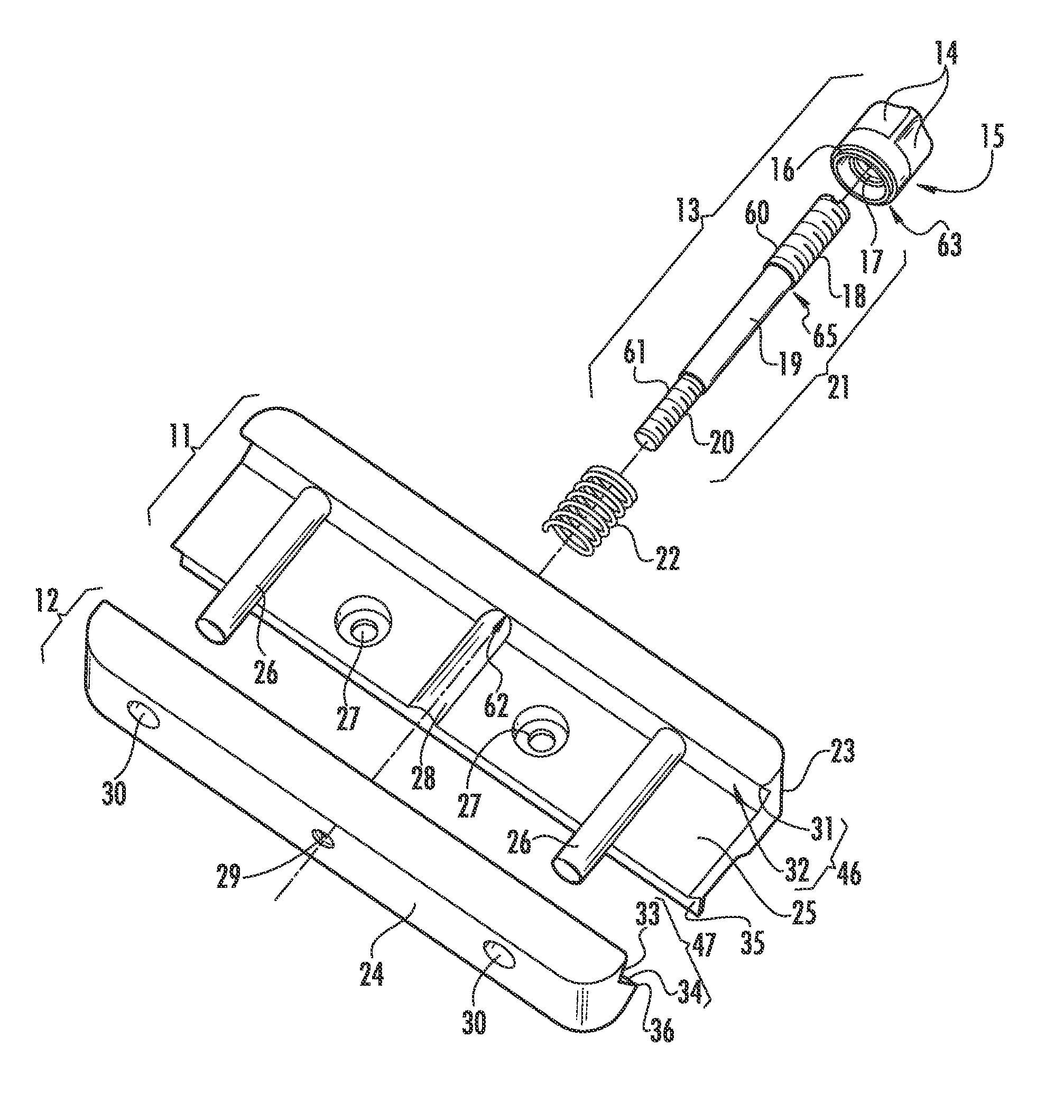
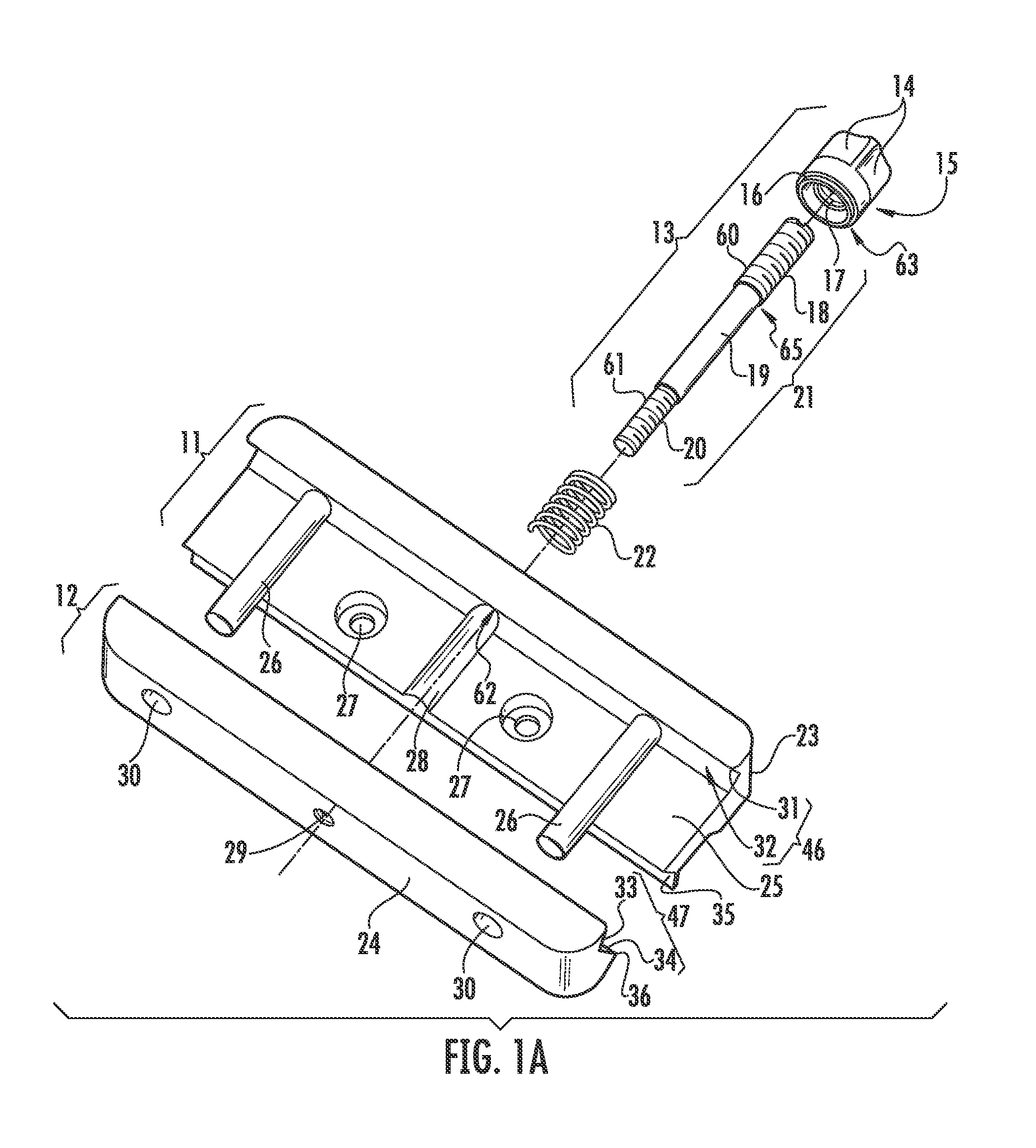
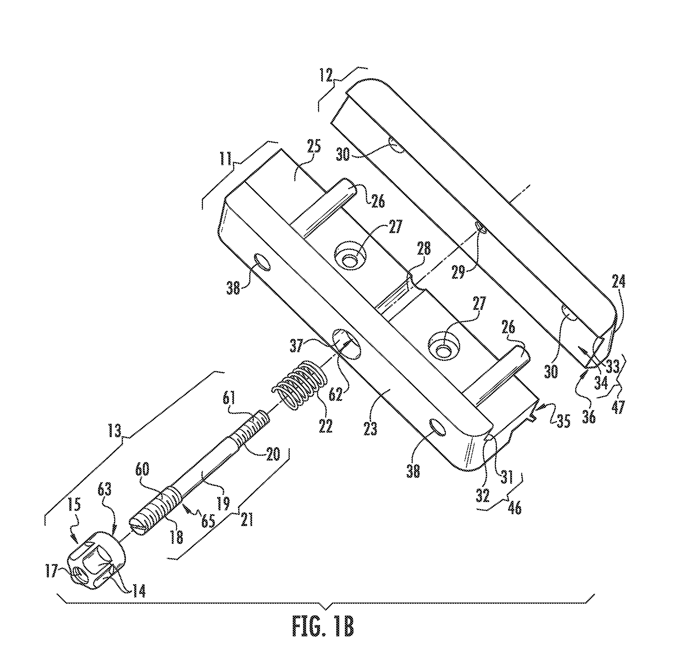
[0039]Referring now to FIGS. 1A-6, an exemplary embodiment of a mount adapter device in accordance with the present disclosure is illustrated and generally includes a push rod member 13, a resilient member 22, a first base member 11, and a second base member 12.

[0040]The push rod member 13 includes a knob 15 fastened to a first end 18 of a shaft 21. The knob 15 includes a centrally threaded aperture 17 therein which allows the knob 15 to be rotated up and down the first end 18 of the shaft 21 of the push rod member 13. The knob 15 may include a design such as the inverse U-shaped depressions 14 illustrated in the depicted embodiment. Such feature provides an attractive design and an additional gripping surface for rotating the knob 15 up and down the first end 18 of the shaft 21. Furthermore, a sealing member 16, such as a plastic gasket, may be disposed around a lower portion 63 of the knob 15 such that, upon assembly of the device 70, the sealing member 16 may be interposed betwee...


PUM


Abstract

A mount adapter device utilizing a spring-loaded push system for quickly and securely attaching accessories to weapon accessory rails is disclosed. The mount adapter device generally includes a first base member, a second base member, a push rod member, and a resilient member. The push rod member connects the first base member and the second base member. The first base member is linearly slidable into engagement with the second base member in a first direction, and the second base member is linearly slidable into engagement with the first base member in a second direction which is opposite the first direction. The first base member includes a first clamping member for engaging a first edge of the weapon accessory rail. The second base member includes a second clamping member for engaging a second edge of the rail. The resilient member provides a spring force and is arranged to force the first clamping member to move in the first direction into locking engagement with the first edge of the rail while simultaneously forcing the second clamping member to move in the second direction into locking engagement with the second edge of the rail.

Description

CROSS-REFERENCE TO RELATED APPLICATIONS[0001]This application is related to and claims priority from earlier filed U.S. Provisional Patent Application No. 61 / 277,864, filed Sep. 30, 2009.BACKGROUND OF THE INVENTION[0002]1. Field of the Invention[0003]The present invention relates generally to mounting devices for attaching various accessories to a support structure. More specifically, the present invention relates to mount adapter devices utilizing a spring-loaded push system for quickly and securely attaching firearm accessories to weapon accessory rails.[0004]2. Description of the Prior Art[0005]Universal weapon accessory rails such as the “Picatinny rail” (i.e., MIL-STD-1913 rail) provide a standardized platform for mounting and dismounting firearm accessories to weapons. Generally, accessories including optics, tactical lights, grenade launchers, night vision devices, and other weapon-mounted accessories are not designed for direct attachment to the rails. Thus, mount adapter de...

Claims


Application Information

Patent Timeline
Patent Type & Authority Patents(United States)
IPC IPC(8): F41C27/00
CPCF41G11/003
Inventor DEROS, MARK A.
Owner SAMAK ENTERPRISES
Why Eureka
Try Eureka