
Heat transfer apparatus

a technology of hydration apparatus and hydration tube, which is applied in the direction of liquid transfer device, light and heating apparatus, air heater, etc., can solve the problems of reducing the insulation effect of hydration apparatus, reducing the insulation effect, and reducing the value of hydration apparatus

Inactive Publication Date: 2012-10-02
LONG MELISSA ANN
View PDF9 Cites 3 Cited by
  • Summary
  • Abstract
  • Description
  • Claims
  • Application Information

AI Technical Summary

Benefits of technology

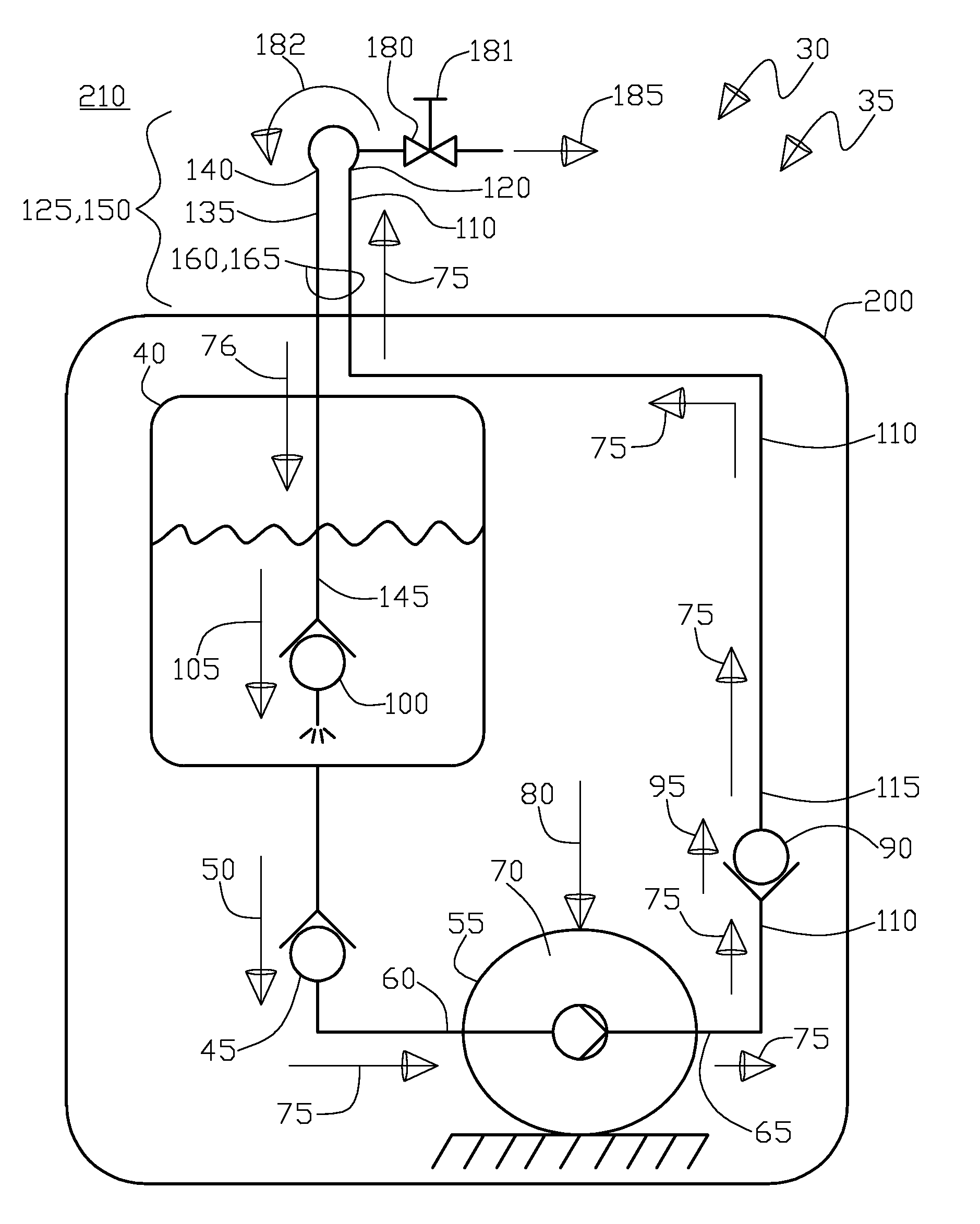
"The present invention is a heat transfer apparatus for a portable hydration system. The apparatus includes a reservoir, a first check valve, a second check valve, a pump, and fluid communication lines. The apparatus also includes a bleed valve that provides intermittent fluid flow to the user for consumption. The technical effects of the invention include equalizing the reservoir and bleed valve temperatures, improving heat transfer efficiency, and providing a more stable and consistent fluid flow rate for the user."

Problems solved by technology

Even though the backpack structure and reservoir combination works well for supporting the somewhat heavy reservoir while the individual is active, an inherent design drawback is that the distance from the reservoir to the user's mouth is long which causes a number of problems, firstly by making hard to suck the fluid through such a long “straw” plus pulling the upward as against gravity, wherein these issues can be enervated by mounting the reservoir higher (for less gravity effect), having a larger diameter tube (for less fluid flow loss), or even pressurizing the reservoir interior by either adding force against the exterior of the reservoir (as the reservoir is typically a flexible member) or internally pressurizing the reservoir, all in an effort to help the drinking fluid flow from the reservoir to the mouthpiece.
Another problem made worse by the long tube occurs in freezing weather, wherein the tube having little thermal mass in typically the worst aspect ratio possible for maximum heat transfer (wherein high heat transfer is undesirable for the freezing environment removing residual heat from the tube) in that the tube has a high surface area to volume ratio by being essentially a long skinny cylinder, all this adds up to the long tube being especially vulnerable to freezing, thus causing the hydration apparatus to be worthless.
Of course insulation can be added to somewhat lessen the tube freezing problem by lengthening the amount of time it takes to freeze the tube, however the insulation around the tube suffers from the same high surface area to volume ratio in that the farther the tube is from the reservoir, the less benefit of the insulation, further the adds bulk and weight, both negatives.
Furthermore, there exists the problem of the mouthpiece being exposed and subject to freezing as the mouthpiece cannot be insulated easily as it need to be exposed to the user's mouth, plus the mouthpiece being the furthest in distance from the reservoir has the least benefit from reservoir heat.
Note that in Mares the need for a separate heat source is a drawback as previously described, by adding complexity and bulk.

Method used


Image

  • Heat transfer apparatus
  • Heat transfer apparatus
  • Heat transfer apparatus

Examples


Embodiment Construction

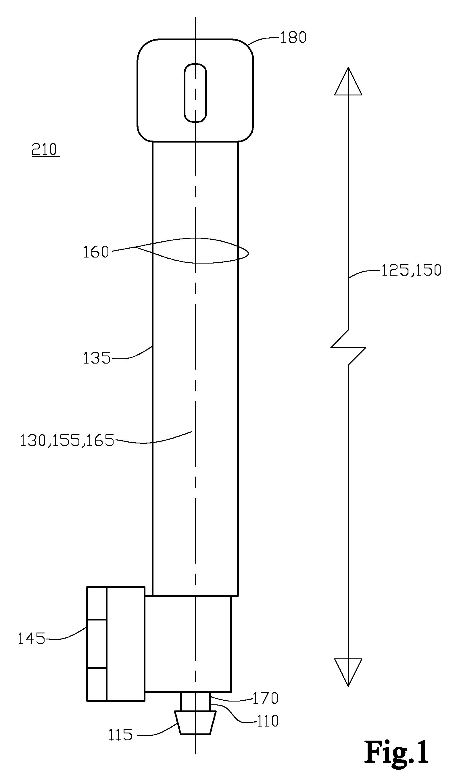
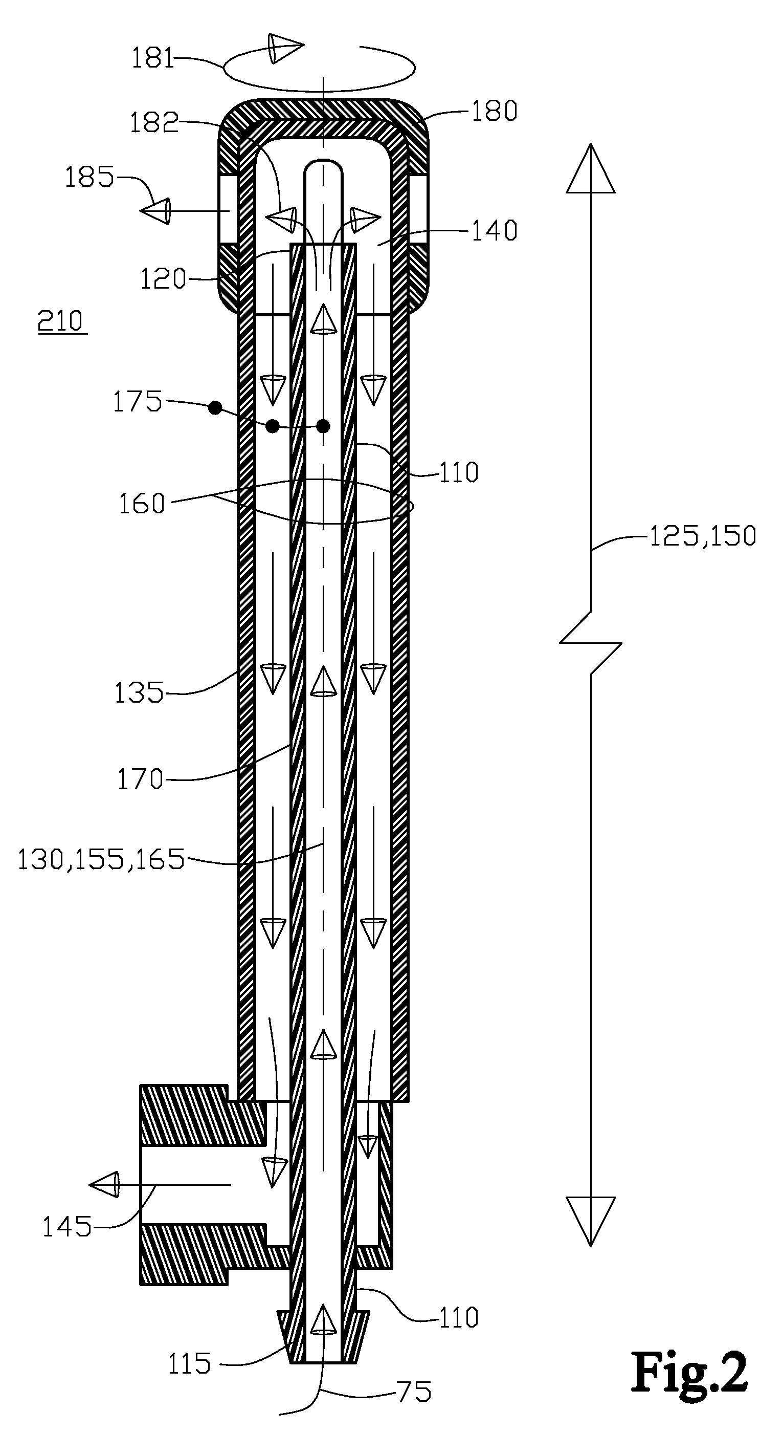
[0064]With initial reference to FIG. 1 shown is an external side elevation view of the first fluid communication line 110, the second fluid communication line 135, and the bleed valve 180, in conjunction with the length of the first 125 and second 150 fluid communication lines with their first 130 and second 155 longitudinal axes. Continuing, FIG. 2 shows a cross sectional view of FIG. 1 with the first fluid communication line 110, the second fluid communication line 135, and the bleed valve 180, in conjunction with the length of the first 125 and second 150 fluid communication lines with their first 130 and second 155 longitudinal axes. Also, in FIG. 2, the fluid flow 75 is from the proximal end portion 115 to the distal end portion 120 of the first fluid communication line 110, recirculation 182 is shown through the bleed valve 180 in the closed operational state, wherein the bleed valve 180 has discharge selectable intermittent flowrate 185, if the bleed valve 180 is in the open ...


PUM


Abstract

A heat transfer apparatus for a portable hydration system that includes a reservoir, a first check valve, a manual pump activated by user movement, a second check valve, a first fluid communication line including a proximal end in communication with the second check valve and a distal end in communication with a bleed valve, further included is a second fluid communication line including an inlet end in communication in the bleed valve and an outlet end in communication with the reservoir. The first fluid communication line and the second fluid communication line are continuously adjacent in position to one another, wherein the bleed valve discharges a selectable intermittent fluid flowrate to the user for consumption and the pump outputs a primary intermittent fluid flowrate greater than the selectable intermittent fluid flowrate, wherein operationally the heat transfer apparatus acts to further help equalize the reservoir and the bleed valve temperatures.

Description

RELATED APPLICATIONS[0001]There are no related applications.TECHNICAL FIELD[0002]The present invention generally relates to a portable hydration apparatus used typically by an individual engaged in a sport related activity. More particularly, the present invention is a heat transfer apparatus that forms a part of a portable hydration apparatus, wherein the portable hydration apparatus is used in a below freezing environment and has a problem of a mouthpiece and potentially the associated fluid communication line freezing that extends from the hydration apparatus reservoir, thus rendering the hydration apparatus non-functional.BACKGROUND OF INVENTION[0003]Typical personal hydration systems usually include a backpack type structure for removably engaging to the individual user. This backpack type structure makes for the most stable and secure attachment system when supporting a fair amount of weight, from the drinking fluid in the reservoir, while the individual is participating in sp...

Claims


Application Information

Patent Timeline
Patent Type & Authority Patents(United States)
IPC IPC(8): B67D7/84
CPCA45F3/16A45F3/04A45F2003/166
Inventor EMENHEISER, MATTHEW C.
Owner LONG MELISSA ANN
Learn More