Backlight assembly and method of manufacturing light guide plate therefor

a backlight assembly and liquid crystal display technology, which is applied in the field of backlight assembly for liquid crystal display devices and the field of manufacturing light guide plates therefor, can solve the problems of increasing the thickness and the manufacturing cost the difficulty of using liquid crystal display, and the deterioration of image quality of liquid crystal display, so as to improve the brightness reduce the number of sheets of the backlight assembly.

Active Publication Date: 2012-10-02
SAMSUNG DISPLAY CO LTD
View PDF8 Cites 11 Cited by
  • Summary
  • Abstract
  • Description
  • Claims
  • Application Information

AI Technical Summary

Benefits of technology

[0011]In accordance with an exemplary embodiment of the present invention a backlight assembly is provided that is capable of improving brightness while reducing the number of sheets employed.
[0029]As a result, brightness of the backlight assembly may be improved and the number of the sheets for the backlight assembly may be reduced.

Problems solved by technology

The liquid crystal display is not a self-emissive device, which is different from other display devices such as cathode ray tubes (CRT), plasma display panels (PDP), field emission displays (FED), or the like, so that the liquid crystal display can become difficult to use under dark conditions in which no light exists.
Typically, the image quality of the liquid crystal display deteriorates as a result of the hot spot.
Further, when various additional parts, such as diffusion sheets, brightness enhancement film, and the like, are used in an attempt to improve the image quality deteriorated by hot spots, the thickness and the manufacturing cost of the liquid crystal display increases.

Method used


Image

  • Backlight assembly and method of manufacturing light guide plate therefor
  • Backlight assembly and method of manufacturing light guide plate therefor
  • Backlight assembly and method of manufacturing light guide plate therefor

Examples


Embodiment Construction

[0041]It will be understood that when an element or layer is referred to as being “on”, “connected to” or “coupled to” another element or layer, it can be directly on, connected or coupled to the other element or layer or intervening elements or layers may be present. Like numbers refer to like elements throughout.

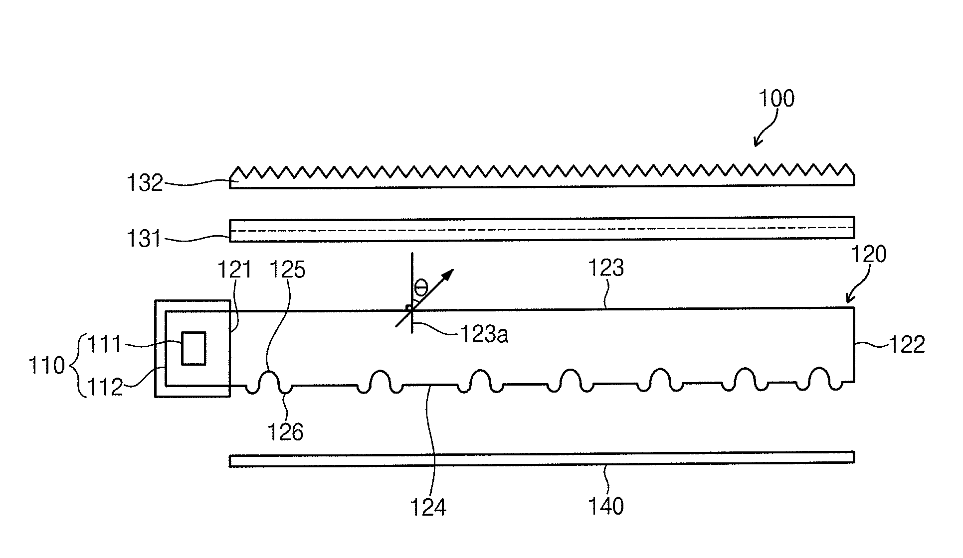
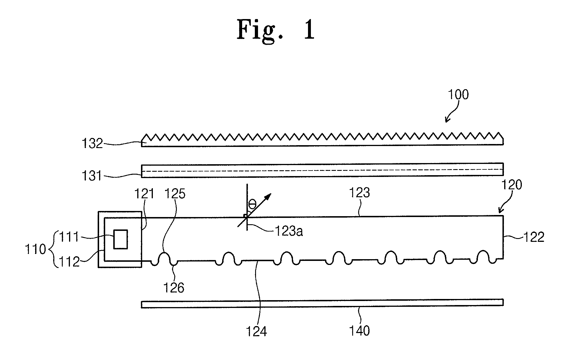
[0042]Referring now to FIGS. 1 and 2, a backlight assembly 100 includes a light source unit 110, a light guide plate 120, a reflection sheet 140, a first prism sheet 131, and a second prism sheet 132.

[0043]The light source unit 110 includes a light source 111 that emits light and a light source cover 112 that covers the light source 111. The light source 111 includes at least one light emitting diode. The light source cover 112 covers the light emitting diode and is partially opened. The light source cover 112 reflects the light emitted from the light emitting diode toward the opened portion thereof. One end of the light guide plate 120 is coupled with the light source cov...


PUM


Abstract

A backlight assembly and a manufacturing method of light guide plate of the backlight assembly is provided. The light guide plate includes an incident surface to which light is incident, an exiting surface from which the light exits, and a reflection surface facing the exiting surface. The light guide plate includes recesses provided on the reflection surface recessed toward the exiting surface to scatter the light. Each of the recesses has a depth-to-width ratio of about 0.2 to about 0.33. Two prism sheets are disposed on the light guide plate. Light exits from the light guide plate at an angle of about 25 degrees to about 30 degrees.

Description

CROSS-REFERENCE TO RELATED APPLICATION[0001]This application claims priority to and the benefit of Korean Patent Application No. 10-2009-0012037 filed on Feb. 13, 2009, the entire content of which is incorporated by reference herein.BACKGROUND[0002]1. Field of the Invention[0003]The present disclosure relates to display devices, and, more particularly, to a backlight assembly for a liquid crystal display device and a method of manufacturing a light guide plate of the backlight assembly.[0004]2. Discussion of the Related Art[0005]In general, a backlight unit for a liquid crystal display serves as an illumination device to uniformly provide light to a liquid crystal display panel of the liquid crystal display. The liquid crystal display panel controls the amount of the light from the backlight assembly to display images.[0006]The liquid crystal display is not a self-emissive device, which is different from other display devices such as cathode ray tubes (CRT), plasma display panels (P...

Claims


Application Information

Patent Timeline
Patent Type & Authority Patents(United States)
IPC IPC(8): F21V7/04
CPCB29D11/00663G02B6/0036G02B6/0065G02F1/1336G02F1/133611
Inventor KIM, HYOUNG-JOOKWON, JAEJOONGSHIM, SUNG-KYU
Owner SAMSUNG DISPLAY CO LTD
Why Eureka
Try Eureka