Filter dust collector

a dust collector and filter technology, applied in the direction of separation process, filtration separation, transportation and packaging, etc., can solve the problems of reduced air passing through the filter medium, difficulty in removing fine particles, and dust in the filter medium, so as to improve the removal efficiency, reduce noise, and increase the effect of filtration amoun

Active Publication Date: 2012-10-02
CHO YONG LAE
View PDF5 Cites 4 Cited by
  • Summary
  • Abstract
  • Description
  • Claims
  • Application Information

AI Technical Summary

Benefits of technology

[0019]In the filter dust collector according to the embodiment of the present invention, dust is removed by spraying compressed air to the filter cloths of the filters in which dust is accumulated while vertically transferring the filter body part. Accordingly, it is possible to improve removal efficiency and increase a filtration amount since there is no interference with flow of the filtered air. Further, since high-pressure compressed air is not sprayed, noise is reduced, and since there is no interference with filtration flow, it is possible to improve a filtration amount even without an increase in facilities, thereby offering an effect of reducing the manufacturing costs.
[0020]Further, the filter dust collector according to the embodiment of the present invention includes the filter bodies having a plurality of filter insertion holes into which a plurality of filters are inserted, the transfer part formed at the center of the filter body part to transfer the filter bodies, and the compressed air supply lines formed at the outer peripheries of the filter insertion holes of the filter bodies to spray the compressed air toward the filters. Accordingly, dust is removed by spraying compressed air to the filters on which dust is accumulated while vertically transferring the filter body part. As the compressed air is sprayed toward an outer portion with accumulated dust, it is possible to easily remove the dust without temporarily operating the compressed air with strong pressure due to excellent dust removal efficiency. Thus, it is possible to improve dust removal efficiency and also increase a life span by reducing impulses of the filters, thereby offering an effect of minimizing waste of resources by using the compressed air at a lower pressure.
[0021]Further, the filter dust collector according to the embodiment of the present invention removes dust by spraying the compressed air to the outside of the filters for collecting dust. Since the compressed air is supplied in the same direction as the direction of air flow in filtration to remove the dust, the dust is collected in the filters and can be removed without interference with air flow for the dust collector which discharges clean air. Since there is no increase in capacity due to reduction in air flow, it is possible to reduce cost of facilities. Also, it is possible to decrease a time period for which the use of the filters is stopped according to removal of dust, thereby offering effects of increasing processing capacity and reducing production costs.
[0022]Further, the filter dust collector according to the embodiment of the present invention includes a plurality of compressed air supply holes formed on the compressed air supply lines installed at the outer peripheries of the filter insertion holes of the filter bodies in the direction of the filters. The compressed air is supplied toward the filters and the compressed air supply lines are connected to the compressed air supply source at the outside of the housing to control the flow by the compressed air valve. As the flow of the compressed air is controlled by the compressed air valve according to the demands, an operator can control dust removal of the filters. Accordingly, there is an effect of increasing removal efficiency by sequentially removing the dust according to the demands.
[0023]Further, the filter dust collector according to the embodiment of the present invention includes the supply spray nozzles having the inclined spray portions formed in the compressed air supply holes of the compressed air supply lines to spray the compressed air toward the filters, thereby providing an effect of improving dust removal efficiency by increasing the spray pressure of the compressed air.
[0024]Further, according to the embodiment of the present invention, a plurality of filter dust collectors are formed by connecting supply ports for supplying filtered air at upper portions of the housings, each having the supply controller rotatably coupled to a supply hinge to control a supply amount. In a state of closing the supply controller of any one of the filter dust collectors with a lot of accumulated dust, the dust is pressed by the compressed air and is discharged through the dust discharge port. When the discharge of dust is finished, the supply port is opened to perform an operation of supplying filtered air, and a removal operation is performed in another one of the filter dust collectors with a lot of accumulated dust. Accordingly, the removal operation is conducted alternately in the filter dust collectors, thereby providing an effect of increasing dust removal efficiency.

Problems solved by technology

Relatively large particles can be easily removed, but it is difficult to remove fine particles which may have a bad influence on a human body.
However, if the dust accumulated on the surface of the filter medium is excessively thick, an amount of air passing through the filter medium is reduced and the holes of the filter medium may be clogged with dust.
In this case, very large noise is generated to damage the work environment.
Consequently, a large-capacity pump should be used to make the amount of dust entering in the filter cloth through attraction holes equal to the amount when the compressed air is not supplied, thereby increasing the manufacturing costs.
Meanwhile, the dust collecting operation is stopped and the removal operation is performed to prevent backflow of dust coming through the attraction holes, but in this case, air purification performance is reduced.

Method used


Image

  • Filter dust collector
  • Filter dust collector
  • Filter dust collector

Examples


Embodiment Construction

[0035]Hereinafter, embodiments of the present invention will be described in detail with reference to the accompanying drawings to allow those skilled in the art to easily use the invention. However, the present invention may be embodied in various different forms and the following embodiments are not limited thereto. Throughout the specification, similar parts are designated by the same reference numerals.

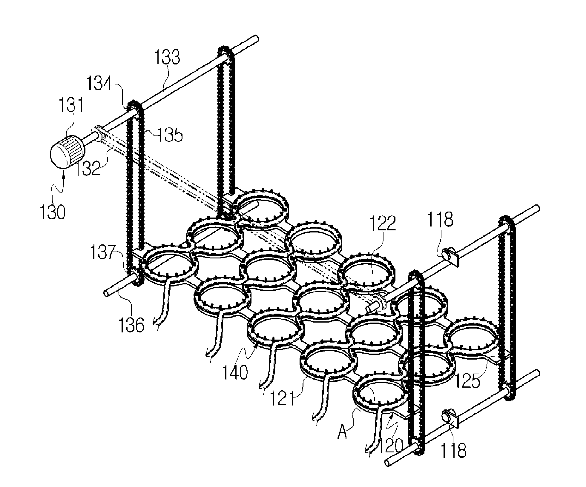
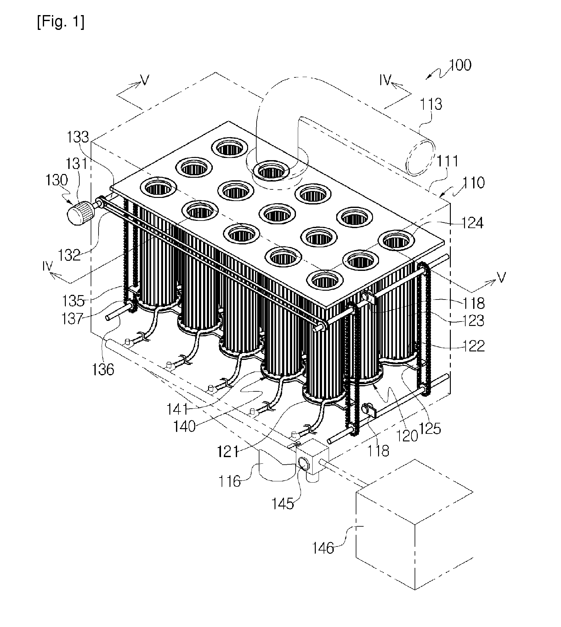
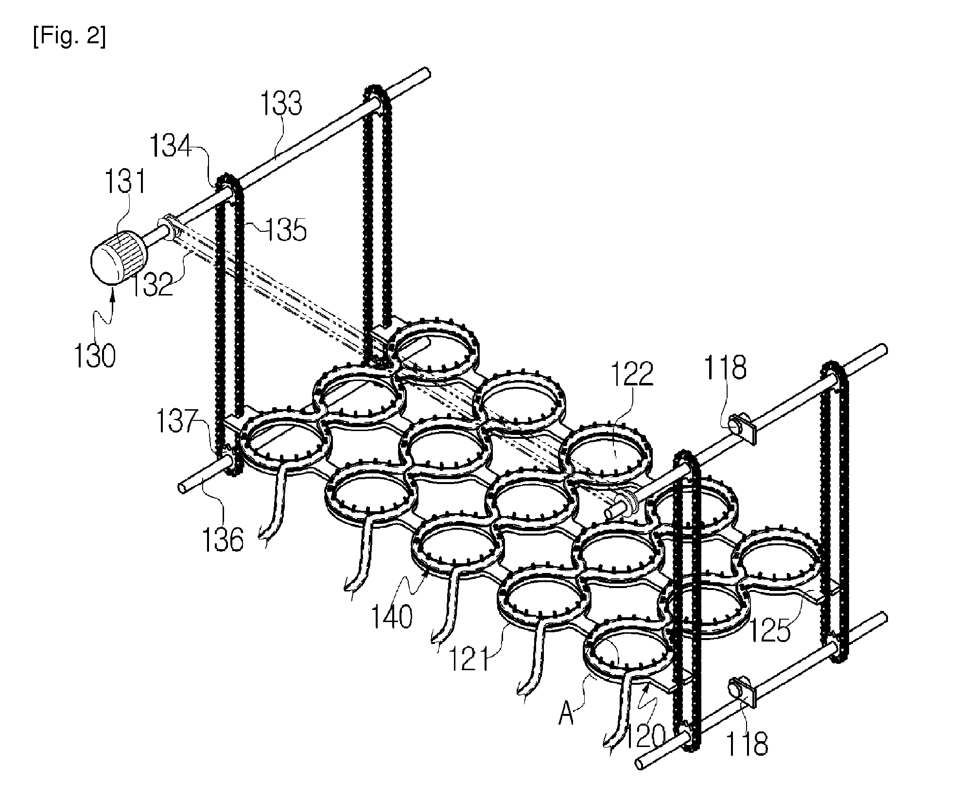
[0036]FIG. 1 illustrates a perspective view of a filter dust collector according to one embodiment of the present invention. FIG. 2 illustrates a perspective view of a filter body part and a transfer part of FIG. 1. FIG. 3 illustrates an enlarged view of a portion indicated by a circle A as shown in FIG. 2. FIG. 4 illustrates a cross-sectional view taken along a line IV-IV of the filter dust collector shown in FIG. 1. FIG. 5 illustrates a cross-sectional view taken along a line V-V of the filter dust collector shown in FIG. 1. FIG. 6 illustrates an enlarged view of a portion indic...


PUM

PropertyMeasurementUnit
sizeaaaaaaaaaa
sizeaaaaaaaaaa
thickaaaaaaaaaa

Abstract

A filter dust collector is disclosed. The filter dust collector includes a housing, filter cloths fixed to an inside of the housing, a filter body part disposed inside the housing and having filter insertion holes, a compressed air supply part coupled to peripheries of the filter insertion holes, a transfer part connected to the filter body part to move the filter body part and the compressed air supply part in a longitudinal direction, a duct suction port formed on a side surface of the housing to suck air to be filtered, a supply port formed on a side surface of the housing to discharge filtered air, and a dust discharge port formed on a side surface of the housing, wherein the filter cloths are positioned at the filter insertion holes, the filter body part and the compressed air supply part move in the longitudinal direction, and the compressed air supply part sprays compressed air to the filter cloths.

Description

TECHNICAL FIELD[0001]The present invention relates to a filter dust collector.BACKGROUND ART[0002]Generally, a dust collector is an apparatus which collects and removes gaseous or liquid fine particles floating in gas. In the first place, the dust collector was used to remove fine particles of ash contained in flue gas of a boiler. Recently, the dust collector is mounted on many chimneys of a factory to prevent sooty smoke and other fine particles from coming out of the chimneys. The fine particles have a size of about 1 mm to 1 μm. Relatively large particles can be easily removed, but it is difficult to remove fine particles which may have a bad influence on a human body. Dust collecting methods include a method using gravity, a filtering method using filter media, a method using inertia or a centrifugal force, a method using sound waves, a cleaning method and the like, and may be largely classified into mechanical methods and electrical methods. The mechanical methods include a dr...

Claims


Application Information

Patent Timeline
Patent Type & Authority Patents(United States)
IPC IPC(8): B01D46/04
CPCB01D46/0065B01D46/2403B01D46/682B01D46/04
Inventor CHO, YONG-LAE
Owner CHO YONG LAE
Why Eureka
Try Eureka