
Particle inspection and removal apparatus and particle inspection and removal program

a particle removal and particle technology, applied in the direction of photomechanical treatment originals, semiconductor/solid-state device testing/measurement, instruments, etc., can solve the problems of affecting the work efficiency of users, affecting the accuracy of particle removal results, so as to reduce the work burden of users, eliminate the determination error, and prevent the effect of a substrate from being damaged

Inactive Publication Date: 2012-10-02
HORIBA LTD
View PDF6 Cites 0 Cited by
  • Summary
  • Abstract
  • Description
  • Claims
  • Application Information

AI Technical Summary

Benefits of technology

[0011]The present invention has been made to solve all the conventional problems. It is a main object of the present invention to lessen work burden on a user, to eliminate determination error, and to prevent prolonged working time by automatically determining whether or not a particle to be removed is present.
[0017]The particle inspection and removal apparatus configured as stated above determines whether to remove a particle for every region of the substrate surface by setting the condition for each region of the substrate surface and removing the particle only if the magnitude of the particle exceeds the condition. It is possible to dispense with unnecessary particle removal operation. Therefore, the number of times of cleaning of the substrate including the particle removal operation can be reduced, working time can be prevented from being prolonged, and running cost can be reduced. In addition, the particle inspection and removal apparatus automatically determines such particle information as the magnitude of the particle or the number of particles without causing a user to make such a determination. Therefore, it is possible to eliminate determination error of each user. Besides, not the user but the particle inspection and removal apparatus performs the removal operation mechanically. This can lessen burden on the user, reduce risk of damage of the substrate W, and dispense with removal skill.
[0018]It is preferable that the substrate is a reticle for transferring a circuit pattern onto a semiconductor wafer or a reticle with a pellicle, and that the regions are set for different circuit patterns formed on the reticle. If the substrate is a reticle for transferring a circuit pattern onto a semiconductor wafer or a reticle with a pellicle, and the regions are set for different circuit patterns formed on the reticle, advantages of the present invention can be exhibited more conspicuously even if the allowed magnitude of the adhering particle differs depending on a size of a circuit pattern formed on the reticle. In addition, the pellicle-attached reticle has the problem that the pellicle is easily damaged particularly if the user cleans the pellicle. In contrast, by causing the particle inspection and removal apparatus to perform particle removal operation, it is possible to prevent the pellicle from being damaged, to reduce the number of times of pellicle replacement, and to greatly reduce running cost. Besides, by determining whether or not to allow an adhering particle for every circuit pattern, it is possible to reduce the number of times of cleaning, to prolong a service life of the circuit pattern itself formed on the reticle, and to thereby reduce cost required for the reticle.
[0020]According to the present invention constituted as stated above, it is possible to lessen work burden on a user, to eliminate determination error, to prevent a substrate from being damaged, and to prevent prolonged working time by automatically determining whether or not a particle to be removed is present.

Problems solved by technology

However, when the particle adhering onto the surface of the substrate is removed by user's manual operation, the substrate is possibly damaged.
If the substrate is a reticle with a pellicle, extreme caution is required to remove the particle by manual operation because a pellicle tends to be damaged.
Furthermore, since a user determines whether to remove the particle, to confirm whether or not it is necessary to perform a particle removal operation is disadvantageously complicated.
Besides, there is a possible determination error depending on the user, and some user possibly overlooks the particle to be removed.
If the uniform determination is made to detect a particle of a predetermined size uniformly, a removal operation for removing a particle that is not always necessary to remove is performed, disadvantageously resulting in an increase in working time.Patent document 1: Japanese Unexamined Patent Publication No. 2006-10544Patent document 2: Japanese Unexamined Patent Publication No. 2006-300705

Method used


Image

  • Particle inspection and removal apparatus and particle inspection and removal program
  • Particle inspection and removal apparatus and particle inspection and removal program
  • Particle inspection and removal apparatus and particle inspection and removal program

Examples


Embodiment Construction

[0026]A particle inspection and removal apparatus according to an embodiment of the present invention will be described hereinafter.

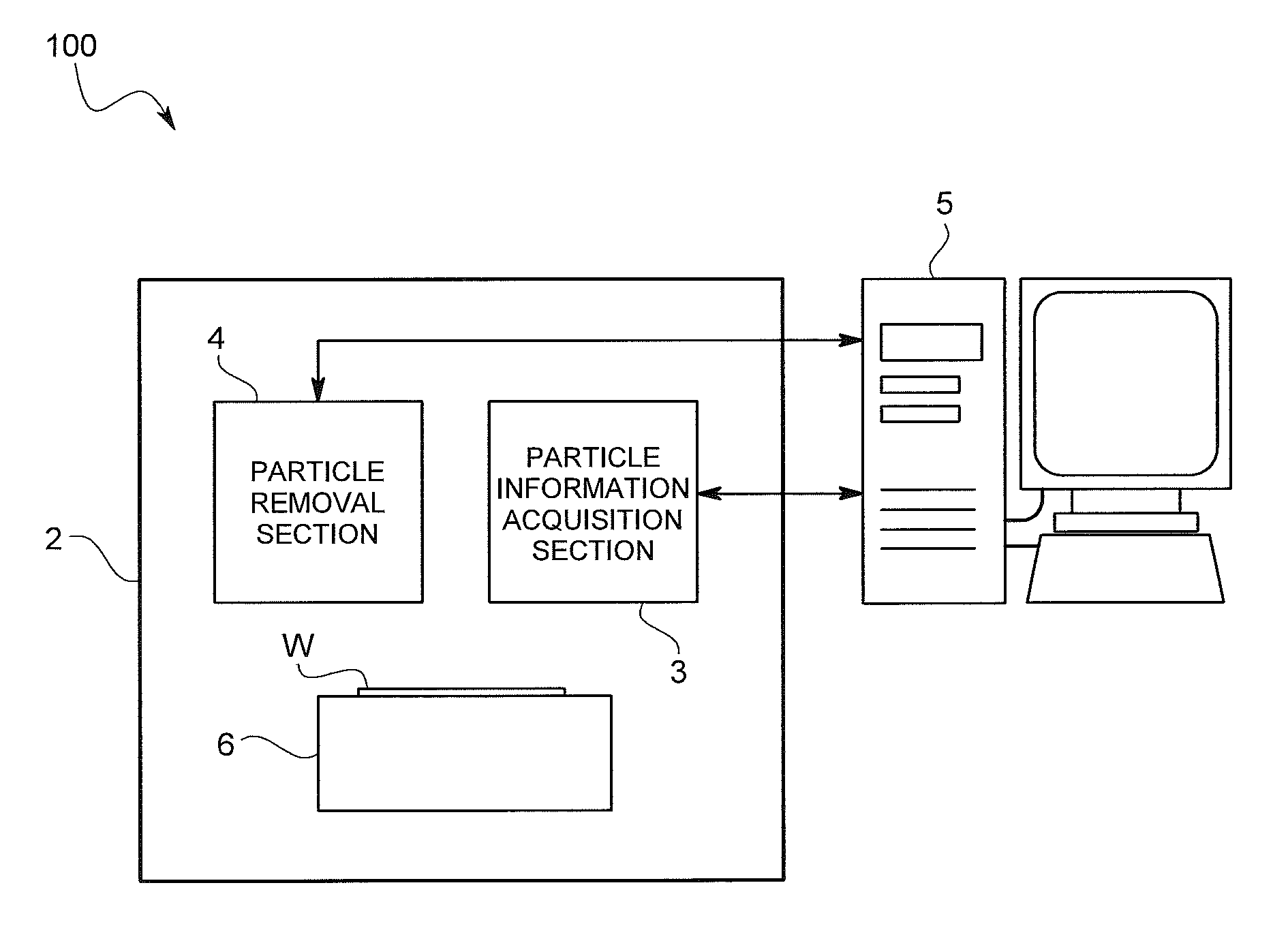
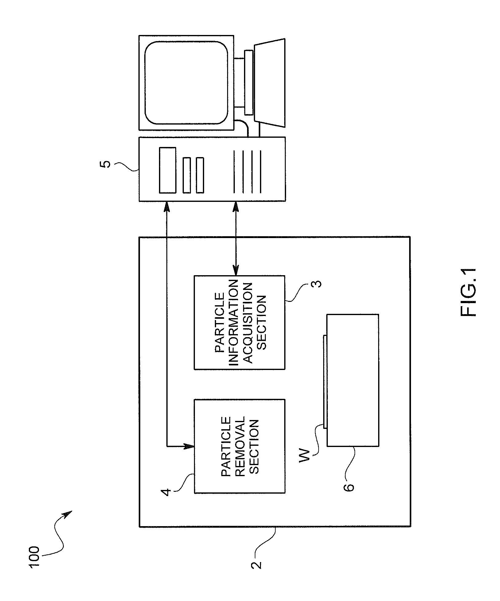
[0027]A particle inspection and removal apparatus 100 according to the embodiment of the present invention inspects and removes a particle that adheres onto a surface W1 (also referred to as “substrate surface W1”, hereinafter) of a substrate W that is a reticle for transferring a circuit pattern onto, for example, a semiconductor wafer, onto which reticle a pellicle serving as a protection film is attached and that is observed in the pellicle. As shown in FIG. 1, the particle inspection and removal apparatus 100 includes a mount 2, a particle information acquisition section 3 acquiring particle information on the substrate surface W1, a particle removal section 4 removing a particle adhering onto the substrate surface W1, and an information processing device 5 acquiring an output signal from the particle information acquisition section 3, calculates th...


PUM

PropertyMeasurementUnit
light intensityaaaaaaaaaa
sizeaaaaaaaaaa
light scatteringaaaaaaaaaa

Abstract

The present invention is to lessen work burden on a user, to eliminate determination error, to prevent a substrate from being damaged, and to prevent prolonged working time by automatically determining whether or not a particle to be removed is present. A particle inspection and removal apparatus of the present invention includes a particle information acquisition section acquiring particle information on a particle adhering onto a substrate surface, a particle removal section removing the particle adhering onto the substrate surface, a comparison section comparing a threshold set for each of regions of the substrate surface with the particle information on each of the region obtained by the particle information acquisition section, and a particle removal control section controlling the particle removal section to remove the particle on the substrate surface based on a comparison result of the comparison section.

Description

BACKGROUND OF THE INVENTION[0001]1. Field of the Invention[0002]The present invention relates to a particle inspection and removal apparatus and a particle inspection and removal program for inspecting a particle adhering onto a surface of a substrate such as a reticle for transferring a circuit pattern onto a semiconductor wafer and removing the particle.[0003]2. Description of the Background Art[0004]As a particle inspection apparatus inspecting a particle on a surface of a substrate, there is known the following particle inspection apparatus as disclosed in Patent document 1. The particle inspection apparatus includes an irradiation optical system irradiating inspection light onto the surface of the substrate, a detection optical system detecting reflected and scattered light by the surface of the substrate, and an information processing device determining whether or not a particle is present on the surface of the substrate based on a light intensity signal obtained by the detect...

Claims


Application Information

Patent Timeline
Patent Type & Authority Patents(United States)
IPC IPC(8): G01N21/00G01N21/956G03F1/84
CPCG01N21/94H01L21/67253H01L21/67288H01L22/12H01L22/20G01N2021/1748G01N2021/945G01N2021/95676
Inventor KANZAKI, TOYOKIOHTSUKI, KUNIO
Owner HORIBA LTD
Learn More