
Reducing multi-cell interference using cooperative random beam forming

a beam forming and multi-cell technology, applied in diversity/multi-antenna systems, substation equipment, site diversity, etc., can solve problems such as unacceptably high outage rates, mutual interference, and inter-base station interference, and achieve high spectral efficiency, reduce communication outages, and aggressive frequency reuse

Inactive Publication Date: 2012-10-02
ADAPTIX
View PDF5 Cites 59 Cited by
  • Summary
  • Abstract
  • Description
  • Claims
  • Application Information

AI Technical Summary

Benefits of technology

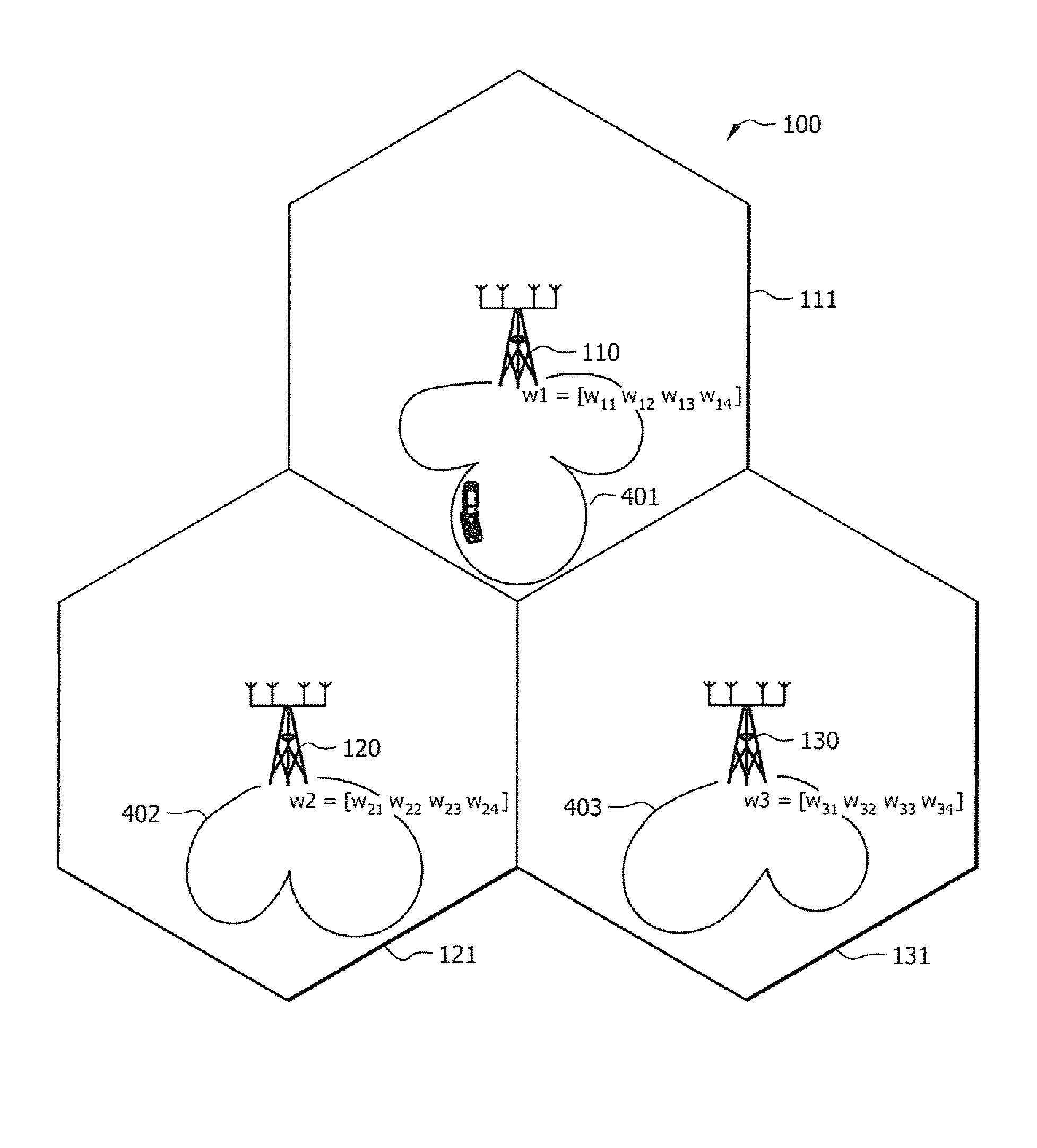
[0012]It should be appreciated that the cooperative operation of the base stations in providing the foregoing randomesque beams will result in reduced communication outages for certain subscriber stations, such as those disposed near a cell's edge, while enabling aggressive frequency reuse. According to embodiments of the invention, a frequency reuse of 1 (i.e., each frequency is reused at each base station of the network) is achievable using the concepts of the present invention, thereby providing a high level of spectral efficiency. Additionally, because low signaling overhead is utilized in providing identification of selected randomesque beams from the subscriber stations to the base station, additional spectral efficiencies are realized according to embodiments of the invention.

Problems solved by technology

In providing pervasive coverage throughout a composite service area, base stations of such communications networks are often disposed in proximity such that inter-base station interference is experienced.
For example, cellular base station deployment patterns used with respect to cellular telephone networks and even some metropolitan area networks (MANs) dispose base stations such that mutual interference is experienced.
Such inter-cell interference can lead to unacceptably high outage rates (i.e., an unacceptably high number of communications which cannot be conducted), decreased throughput rates, decreased signal quality, etc., particularly with respect to subscriber stations disposed near the edge of a cell.
However, such frequency reuse patterns result in substantial spectral inefficiency.
However, appreciable feedback overhead is utilized in providing information for downlink power control from the subscriber stations to their respective base station.
Moreover, such downlink power control not only reduces the signal energy and thus the interference in a neighboring cell, but it also reduces the energy of the signal as received by an intended subscriber station.
Accordingly, many subscriber stations, such as those disposed near the edge of a cell, those in a shadow or signal fade, etc., may experience outages, decreased throughput, decreased signal quality, etc.
However, such circuitry is typically complicated, requiring appreciable knowledge with respect to the interfering signal and / or desired signal for effective cancellation.
Accordingly, such circuitry is often relatively expensive, increasing the cost and complexity of subscriber stations appreciably.
Feedback of CSI generally requires large overhead signaling, and thus results in spectral inefficiency.
Assuming that the downlink has the identical channel as the uplink (e.g., to avoid downlink CSI feedback by measuring uplink CSI at the base station) is often not accurate, particularly in frequency division multiplex (FDM) systems and even time division multiplex (TDM) systems where the subscriber stations are highly mobile or fast moving.
Calibration of RF front end circuitry to compensate for the mismatch between uplink transmitting and downlink receiving circuits is relatively complicated, resulting in appreciably increased implementation and deployment costs.

Method used


Image

  • Reducing multi-cell interference using cooperative random beam forming
  • Reducing multi-cell interference using cooperative random beam forming
  • Reducing multi-cell interference using cooperative random beam forming

Examples


Embodiment Construction

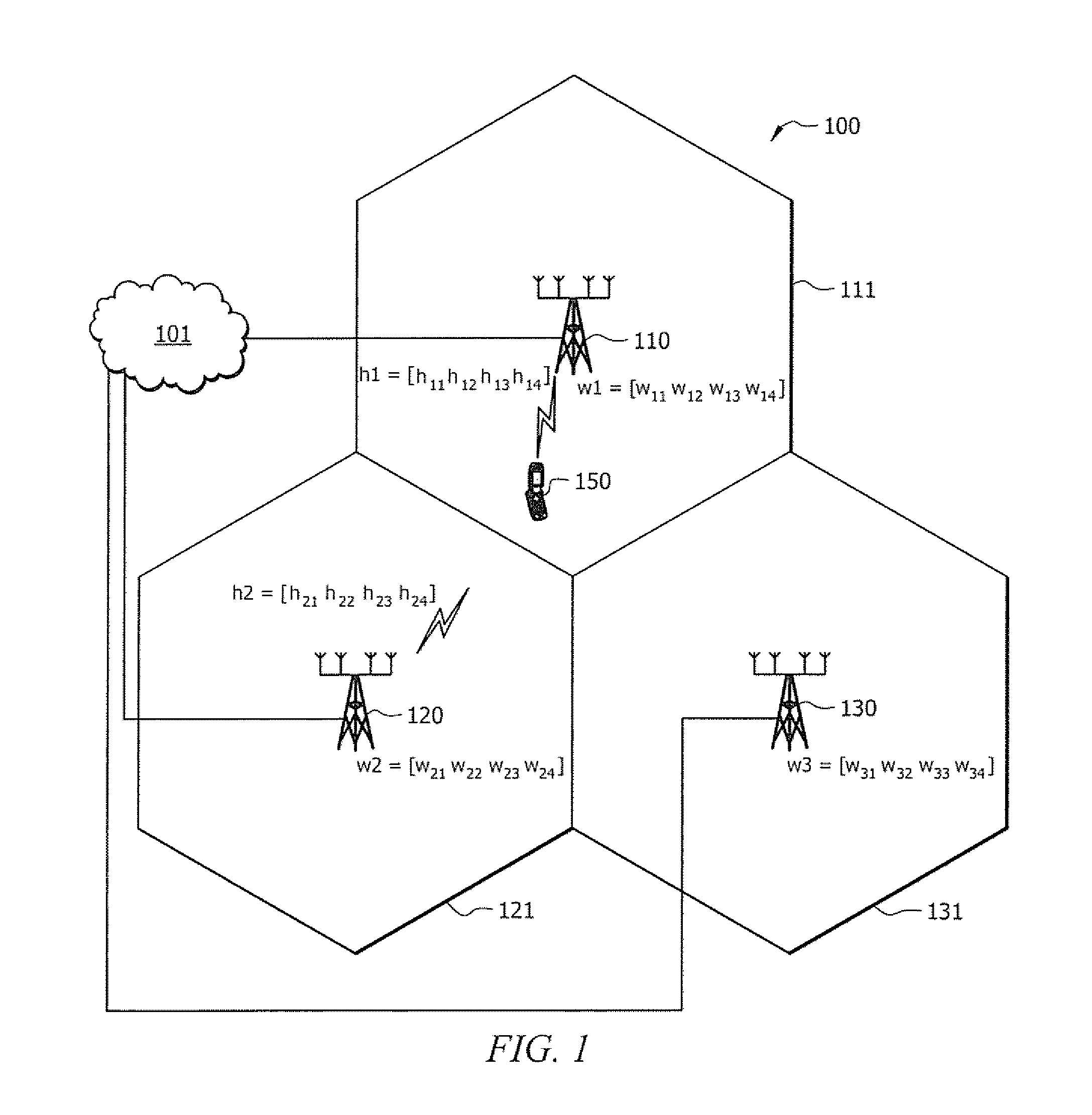
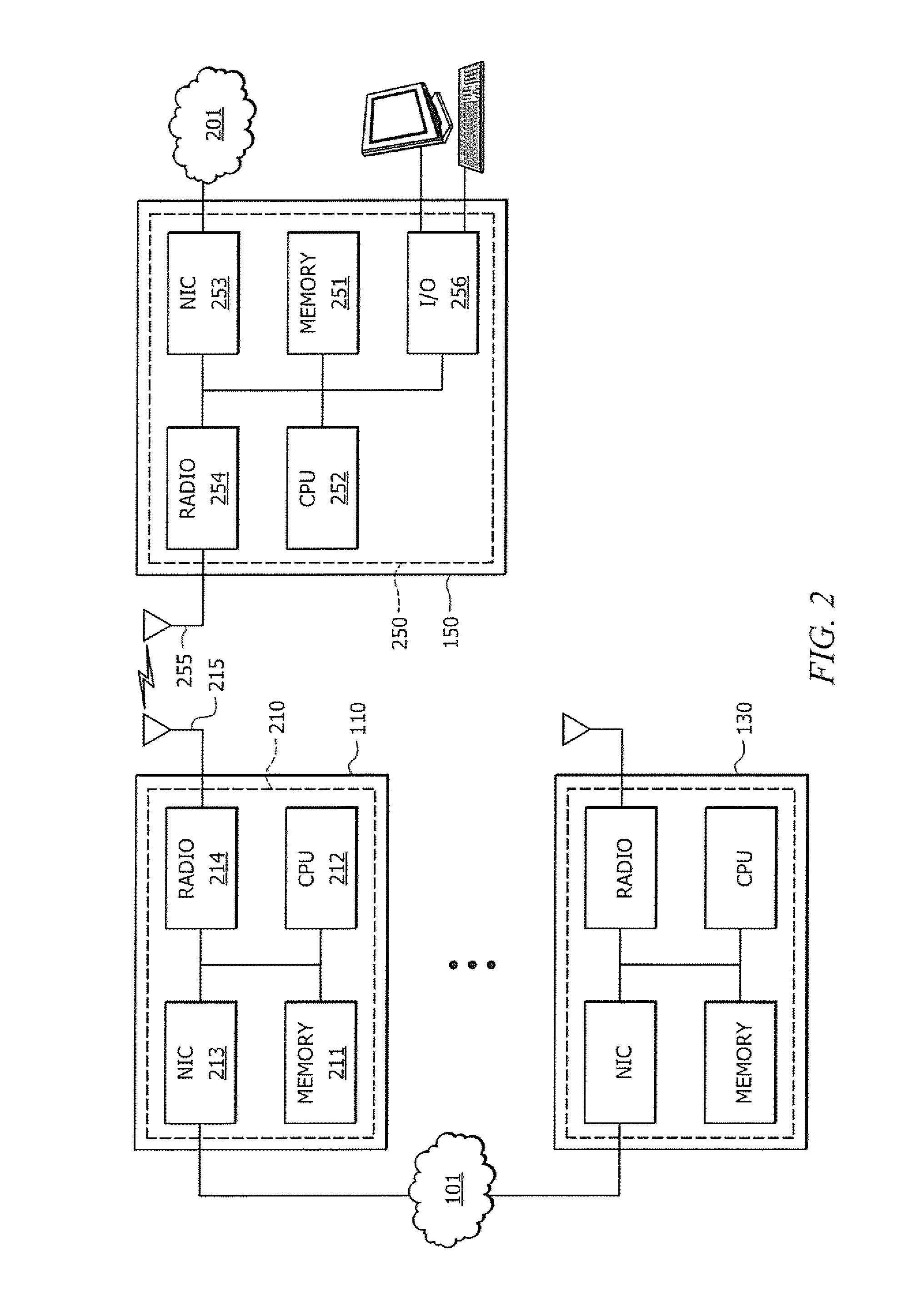
[0019]Directing attention to FIG. 1, communication system 100 adapted according to an embodiment of the present invention is shown. In the illustrated embodiment, communication system 100 includes a plurality of base stations, shown as base stations 110-130, each having a service area associated therewith, shown as cells 111-131 respectively. Subscriber station 150 is disposed within service area 111 of base station 110. Base stations 110-130 of communication system 100 may operate to provide a local area network (LAN), metropolitan area network (MAN), or wide area network (WAN).

[0020]It should be appreciated that communication system 100 of embodiments may include numbers of base stations and / or subscriber stations different than that shown. For example, communication system 100 may comprise a plurality of subscriber stations disposed throughout service areas 111-131. Communication between such subscriber stations and base stations 110-130 may be provided using a number of multiple...


PUM


Abstract

Systems and methods which implement cooperative random or quasi-random beam forming as between a plurality of base stations in a wireless network to reduce multi-cell interference are shown. For example, a plurality of base stations in a wireless network cooperate to provide frequency resources, such as channels, subchannels, subcarriers, etc., in a plurality of randomesque beams. In operation, subscriber stations preferably analyze signals as received on a plurality of the randomesque beams to determine one or more “best” beams for use in communication between the subscriber station and base station. Assuming an identified beam is available for use by the subscriber station, payload communications may be provided using one or more beams identified by the subscriber station as a “best” beam. The base stations of the wireless network preferably cooperate to periodically reform the randomesque beams.

Description

REFERENCE TO RELATED APPLICATIONS[0001]The present application is related to co-pending and commonly assigned U.S. patent application Ser. No. 12 / 037,736 entitled “LOW OVERHEAD SIGNALING FOR IMPLEMENTING SPATIAL DIVISION MULTIPLE ACCESS (SDMA),” filed concurrently herewith, the disclosure of which is hereby incorporated herein by reference.TECHNICAL FIELD[0002]The invention relates generally to wireless communications and, more particularly, to techniques for reducing multi-cell interference using cooperative random or quasi-random beam forming.BACKGROUND OF THE INVENTION[0003]In recent years wireless communication networks having a plurality of base stations or other access points to provide wireless communication links pervasively throughout a composite service area have become almost ubiquitous. In providing pervasive coverage throughout a composite service area, base stations of such communications networks are often disposed in proximity such that inter-base station interferenc...

Claims


Application Information

Patent Timeline
IPC IPC(8): H04M1/00H04B1/38
CPCH04B7/024H04B7/0695H04B7/0606
Inventor SHEN, MANYUANXING, GUANBINSHAO, XUN
Owner ADAPTIX
Learn More