Centrifugal pump

a centrifugal pump and centrifugal pump technology, applied in the direction of motors, electrical devices, dynamo-electric machines, etc., can solve the problems of difficult-to-guaranteed flat support of components on the base, low heat conductance of components, etc., and achieve the effect of exceptional heat discharging effect, easy mounting and secure installation

Active Publication Date: 2012-10-09
BUHLER MOTOR GMBH
View PDF8 Cites 19 Cited by
  • Summary
  • Abstract
  • Description
  • Claims
  • Application Information

AI Technical Summary

Benefits of technology

[0008]This arrangement ensures an exceptional heat discharging effect by virtue of the fact that the heat originating in an electronic component is discharged to the circulation medium of the centrifugal pump through the conductors of the electronic circuit board, the heat conducting medium and the base of the split case.
[0009]An appropriately larger area is available for heat conduction if several components are used. In one variant therefore, at least three transistors are coupled thermally with the base as electronic components. The heat conducting element is preferably a heat conducting foil. Heat conducting foils can be mounted easily and securely.

Problems solved by technology

A disadvantage of this design is the low heat conductance of the component housing and the difficult-to-guarantee flat support of the component on the base.

Method used


Image

  • Centrifugal pump
  • Centrifugal pump
  • Centrifugal pump

Examples


Embodiment Construction

[0030]In describing preferred embodiments of the present invention illustrated in the drawings, specific terminology is employed for the sake of clarity. However, the invention is not intended to be limited to the specific terminology so selected, and it is to be understood that each specific element includes all technical equivalents that operate in a similar manner to accomplish a similar purpose.

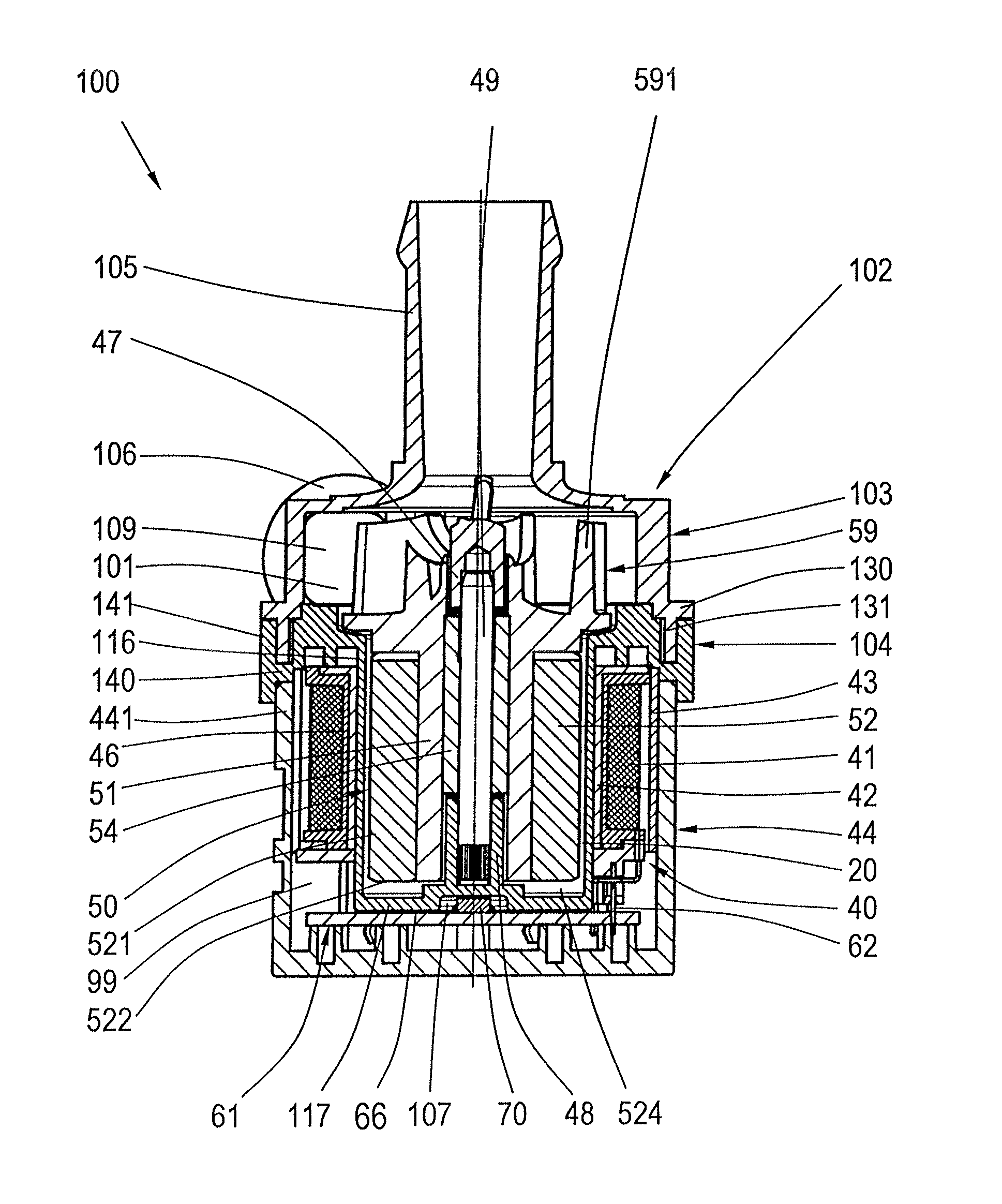
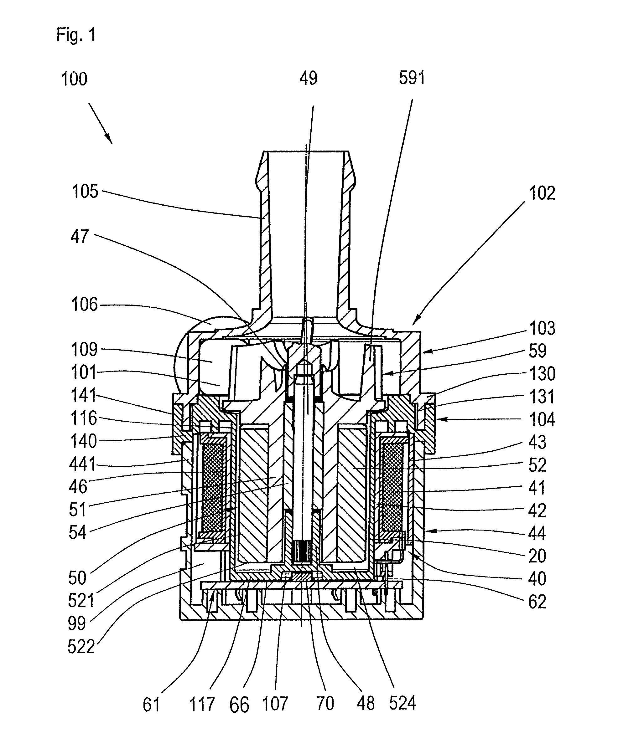
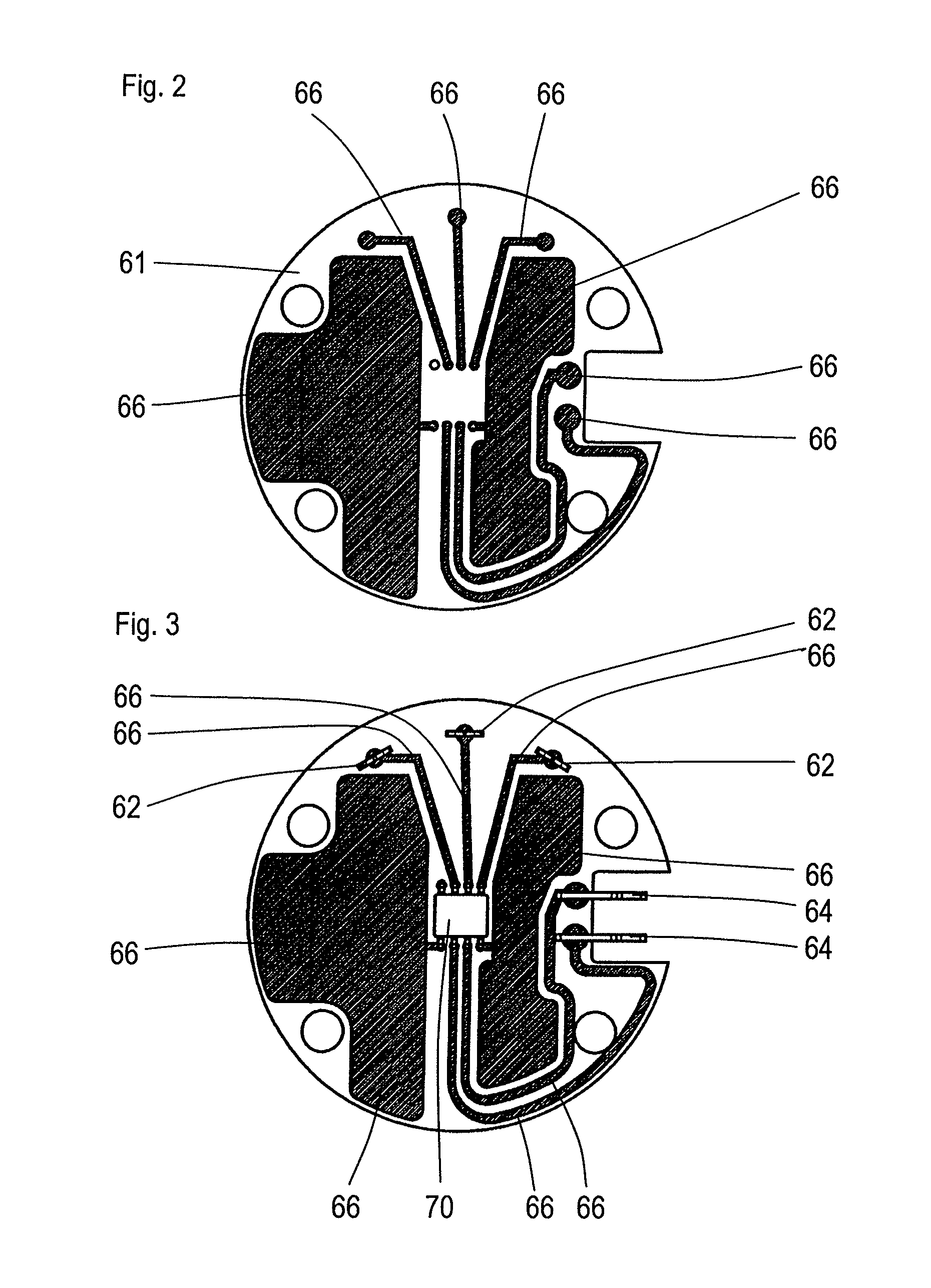
[0031]FIGS. 1 and 10 show a sectional view of a centrifugal pump 100 according to the invention with a pump housing 102 consisting of a first housing section 103 and a second housing section 104 attached to it. A motor housing section 44 limits a dry chamber which is occupied by a stator 40 of an electronically commutated DC motor and its triggering electronics. The motor housing section 44 closes the second housing section 102. The first and second housing sections 103, 104 limit a wet chamber 101 of the centrifugal pump. The second housing section 104 is integrated into a single piece w...


PUM


Abstract

A centrifugal pump with an existing pump housing made of plastic material that can be processed through injection molding, the pump housing having a first housing section featuring a suction nozzle and a pressure nozzle, a second housing section supporting an electronically commutated DC motor and a split case, a motor housing section that closes a dry chamber separated from a wet chamber by the split case in which a stator and electronic components are arranged, and a permanent magnet rotor that is mounted in the wet chamber in such a way that it can rotate, thereby driving a pump impeller that reaches into the pump chamber. The electronic components are arranged on an electronic circuit board parallel to a base of the split case. The electronic circuit board is in heat conducting contact with the base.

Description

BACKGROUND OF THE INVENTION[0001](1) Field of the Invention[0002]The invention is related to a centrifugal pump with a pump housing made of plastic material that can be processed through injection molding having a first housing section containing a suction nozzle and a pressure nozzle, a second housing section supporting an electronically commutated DC motor and having a split case, a motor housing section that closes a dry chamber which is separated from a wet chamber by the split case and in which a stator and an electronic component are arranged, and a permanent magnet rotor mounted in the wet chamber in such a way that it can rotate and drive a pump impeller stretching into the pump chamber. The electronic components are arranged on an electronic circuit board aligned at right angles to an axle and parallel to a base of the split case, and the electronic circuit board is in heat conducting contact with the base.[0003](2) Description of the Related Art[0004]A generic centrifugal ...

Claims


Application Information

Patent Timeline
Patent Type & Authority Patents(United States)
IPC IPC(8): F04B35/04
CPCF04D29/5893F04D13/064F04D13/0686F04D29/5813
Inventor IHLE, OLAIPETERREINS, THOMASSCHMIDT, HELMUTSUTTNER-REIMANN, ARMIN
Owner BUHLER MOTOR GMBH
Why Eureka
Try Eureka