Electronic connector with grounding metal plate

a technology of electronic connectors and metal plates, applied in the direction of coupling device connections, coupling contact member materials, coupling protection earth/shielding arrangements, etc., can solve the problems of large production of electronic connectors, complex soldering operations, false welding, etc., to reduce reduce the manufacturing procedure and the cost of electronic connectors, and facilitate repair and replacement.

Inactive Publication Date: 2012-10-09
CHENG UEI PRECISION IND CO LTD
View PDF4 Cites 4 Cited by
  • Summary
  • Abstract
  • Description
  • Claims
  • Application Information

AI Technical Summary

Benefits of technology

[0014]Because the first connecting portion of each contact and the second connecting portion of the ground terminal can electronically connect to the printed circuit board. Since, it is unnecessary to solder the electronic connector to the printed circuit board. The metal plate and the contact module can be easy inserted into and fastened to the insulating case.
[0015]Therefore, the electronic connector has a simple structure. The fabricating procedure and the cost of the electronic connector can be reduced. It is convenient to repair and replace the electronic connector if the electronic connector is damaged.

Problems solved by technology

Furthermore, the production of the electronic connector becomes large-scale nowadays.
However, the soldering operation is complexly and easy to cause a false weld.
Moreover, it is inconvenience to replace a new electronic connector if an old electronic connector is broke.
The manufacturing procedure is unsuitable in mass production.
Because the shell is made by a metal material, the cost of the electronic connector is thereof increased.
The connection between the metal shell and the insulating housing is infirm to cause the mating connector connecting to the electronic connector incorrectly.

Method used


Image

  • Electronic connector with grounding metal plate
  • Electronic connector with grounding metal plate
  • Electronic connector with grounding metal plate

Examples


Embodiment Construction

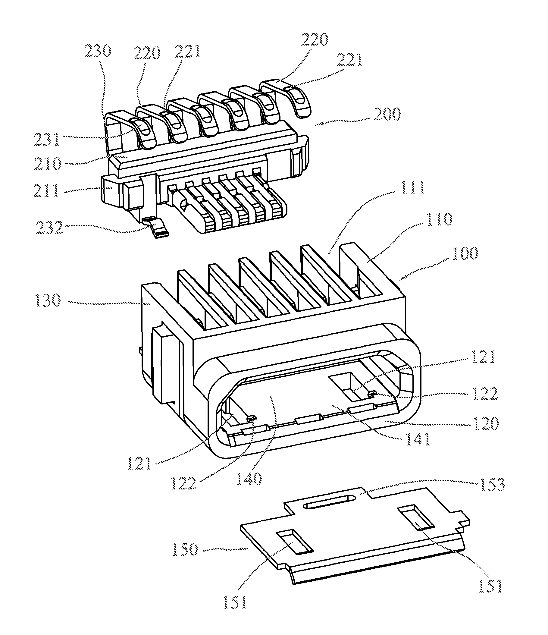
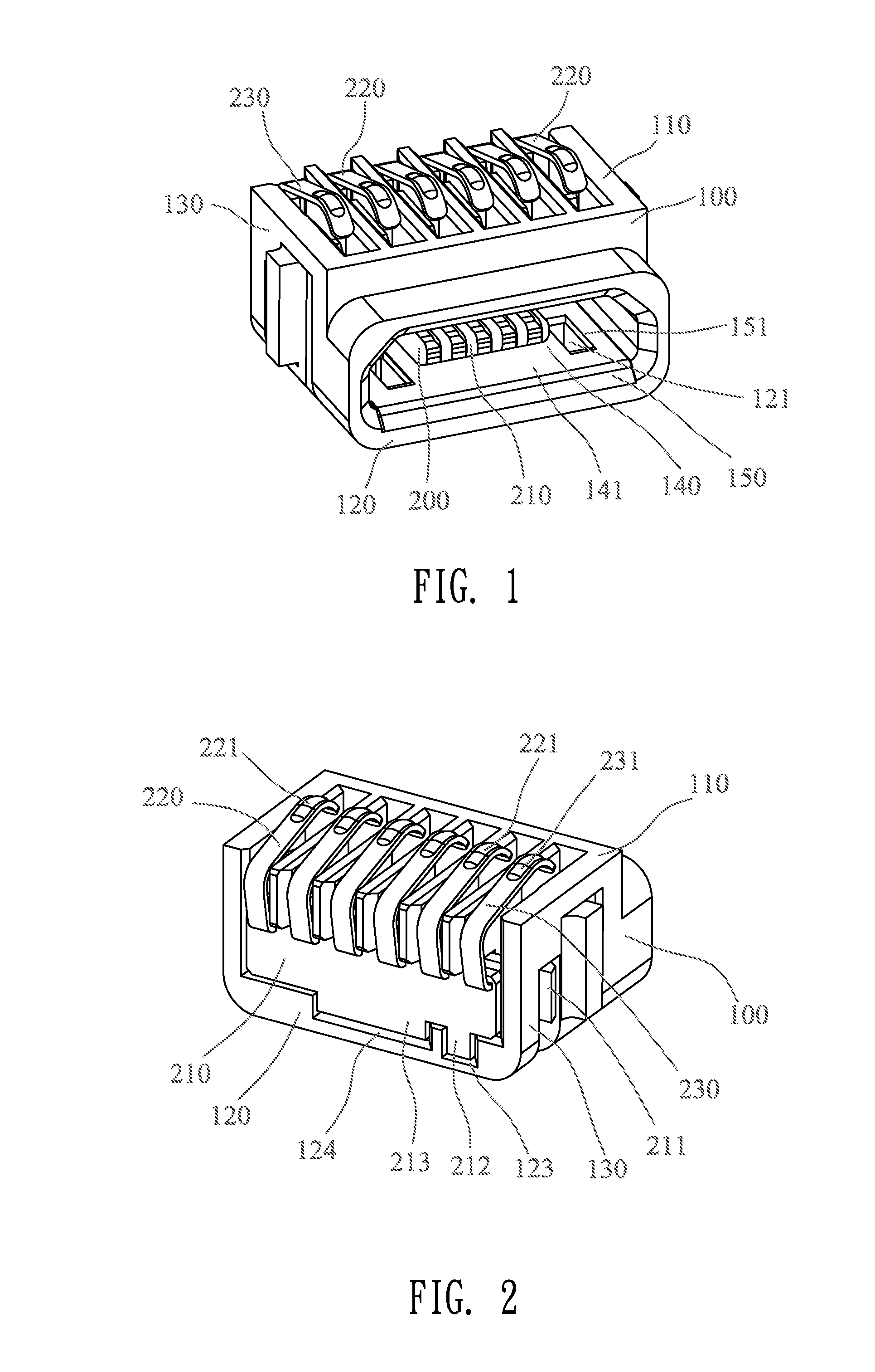
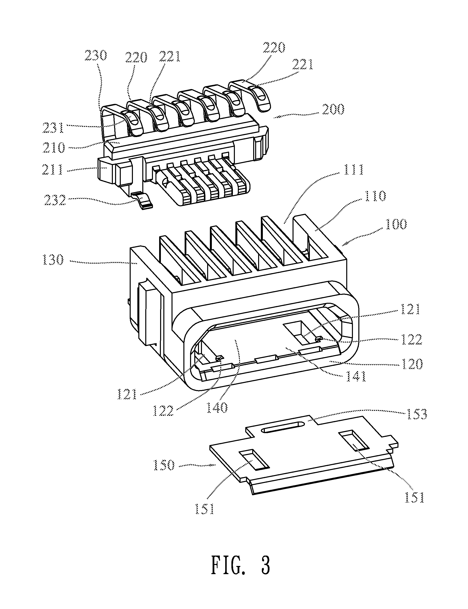
[0023]Please refer to FIG. 1 to FIG. 6. A preferred embodiment of an electronic connector includes an insulating case 100, a metal plate 150 and a contact module 200. The contact module 200 includes an insulating housing 210, a plurality of contacts 220 and a ground terminal 230. The insulating case 100 defines a receiving space 140 for receiving and fastening the contact module 200. The contacts 220 and the ground terminal 230 are respectively fixed to the insulting housing 210. Especially, the contacts 220, the ground terminal 230 and the insulating housing 210 are formed integrally by insert molding.

[0024]The insulating housing 210 includes opposite sides and a projection 211 protruded outwardly from each of the sides. The insulating case 100 includes opposite side surfaces 130 and a through hole 131 defined at each side surface 130. The projection 211 of the insulating housing 210 engages with the through hole 131 of the insulating case 100 for fastening the contact module 200 i...


PUM


Abstract

An electronic connector includes an insulating case, a metal plate and a contact module. The insulating case includes a top surface, a bottom surface, a receiving space defined therein, and a plurality of grooves defined at the top surface. The metal plate is retained in the receiving space and attached to the bottom surface of the insulating case. The contact module is retained in the receiving space, which includes an insulating housing, a plurality of contacts and a ground terminal. Each contact includes a first connecting portion extended above the top surface and aligned with the corresponding groove of the insulating case. The ground terminal includes a second connecting portion and a contacting portion. The second connecting portion is extended above the top surface and aligned with the corresponding groove of the insulating case. The contacting portion is connected to the metal plate.

Description

BACKGROUND OF THE INVENTION[0001]1. Field of the Invention[0002]The present invention relates to an electronic connector, more specifically, to an electronic connector with a simple structure.[0003]2. The Related Art[0004]Nowadays, with development of the electronic products, the connection between the electronic products and the peripheral devices are frequent. The connection is achieved by an electronic connector. Since, the electronic connector is used frequently. Because the electronic connector is widely used, the quality of the electronic connector requested by customers becomes higher. Furthermore, the production of the electronic connector becomes large-scale nowadays.[0005]a conventional electronic connector includes a metal shell, an insulating housing and a plurality of contacts. The insulating housing defines a plurality of grooves for respectively receiving and fixing the contacts. The metal shell encloses the insulating housing and the contacts for preventing the insul...

Claims


Application Information

Patent Timeline
Patent Type & Authority Patents(United States)
IPC IPC(8): H01R12/00H05K1/00
CPCH01R13/6597H01R12/714H01R24/62
Inventor YANG, OUCHEN, PING-CHIHZHANG, HONG-TUCHEN, MING-CHIANG
Owner CHENG UEI PRECISION IND CO LTD
Why Eureka
Try Eureka