Transmission and power generation system having torque reacting joint

a technology of transmission and power generation system, which is applied in the direction of electric generator control, machine/engine, etc., can solve the problems of reducing the size of coupling hardware, and reducing the efficiency of small and efficient wind turbine design, etc., to achieve uniform distribution of reaction load, reduce coupling hardware size, and improve the radial alignment of the gear-train

Inactive Publication Date: 2012-10-16
GENERAL ELECTRIC CO
View PDF11 Cites 11 Cited by
  • Summary
  • Abstract
  • Description
  • Claims
  • Application Information

AI Technical Summary

Benefits of technology

[0006]In this way, by carrying the reaction torque substantially via the mating indents, it is possible that coupling hardware size, as well as transmission housing size, can be reduced. Further, by carrying the reaction torque substantially via the mating indents, the mating surfaces of the first and second sections of the outer housing are more free to flex and / or deform, thus more evenly distributing the reaction load and improving radial alignment of the gear-train in the gearbox.

Problems solved by technology

However, small and efficiently designed wind turbines may be difficult to achieve for a multitude of reasons.
As such, as the power generated by wind turbines continues to rise, so does the reaction torque that is provided by the transmission, thus frustrating the goal of maintaining a small and efficient wind turbine design.
However, in some transmission designs, such as differential planetary gearboxes, the size of the coupling hardware may be restricted due to location, size, etc., of other components included in the transmission.
Further, requirements related to locating, packaging, and servicing the transmission in the wind turbine, and properly installing and mounting the transmission to the wind driven blades and the electric power generation units, may also limit the ability to increase the coupling elements of the transmission housing and / or the size of the transmission housing.

Method used


Image

  • Transmission and power generation system having torque reacting joint
  • Transmission and power generation system having torque reacting joint
  • Transmission and power generation system having torque reacting joint

Examples


Embodiment Construction

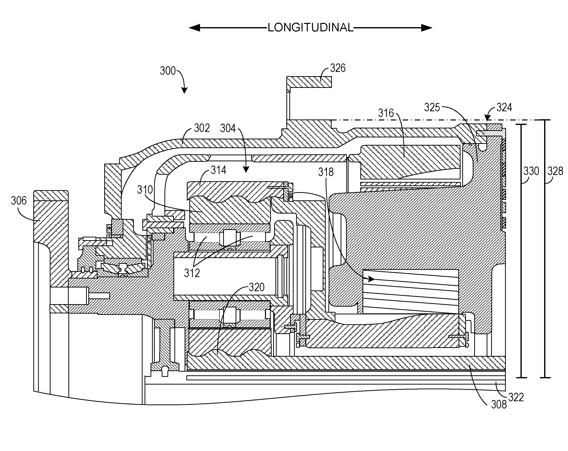
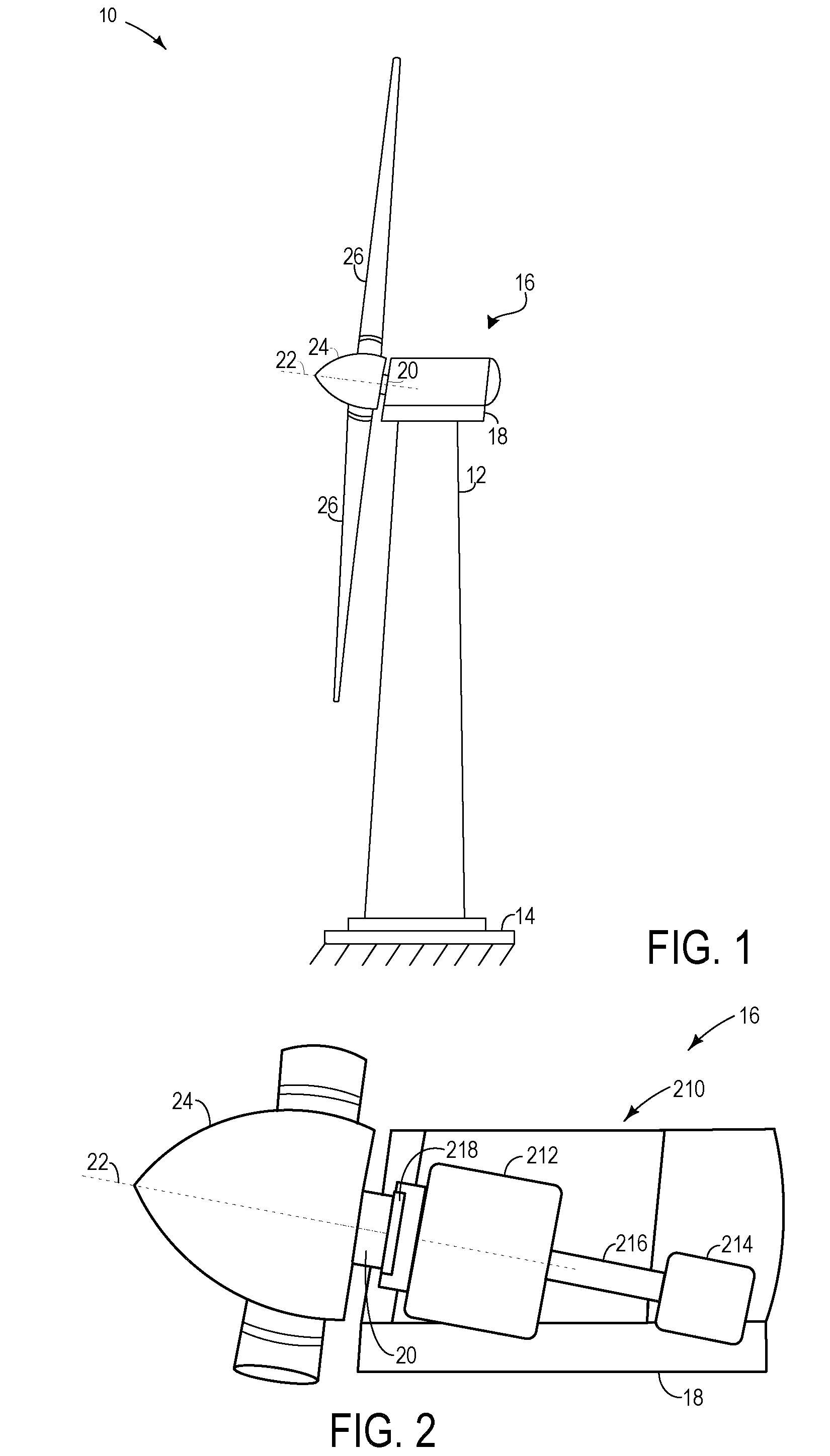
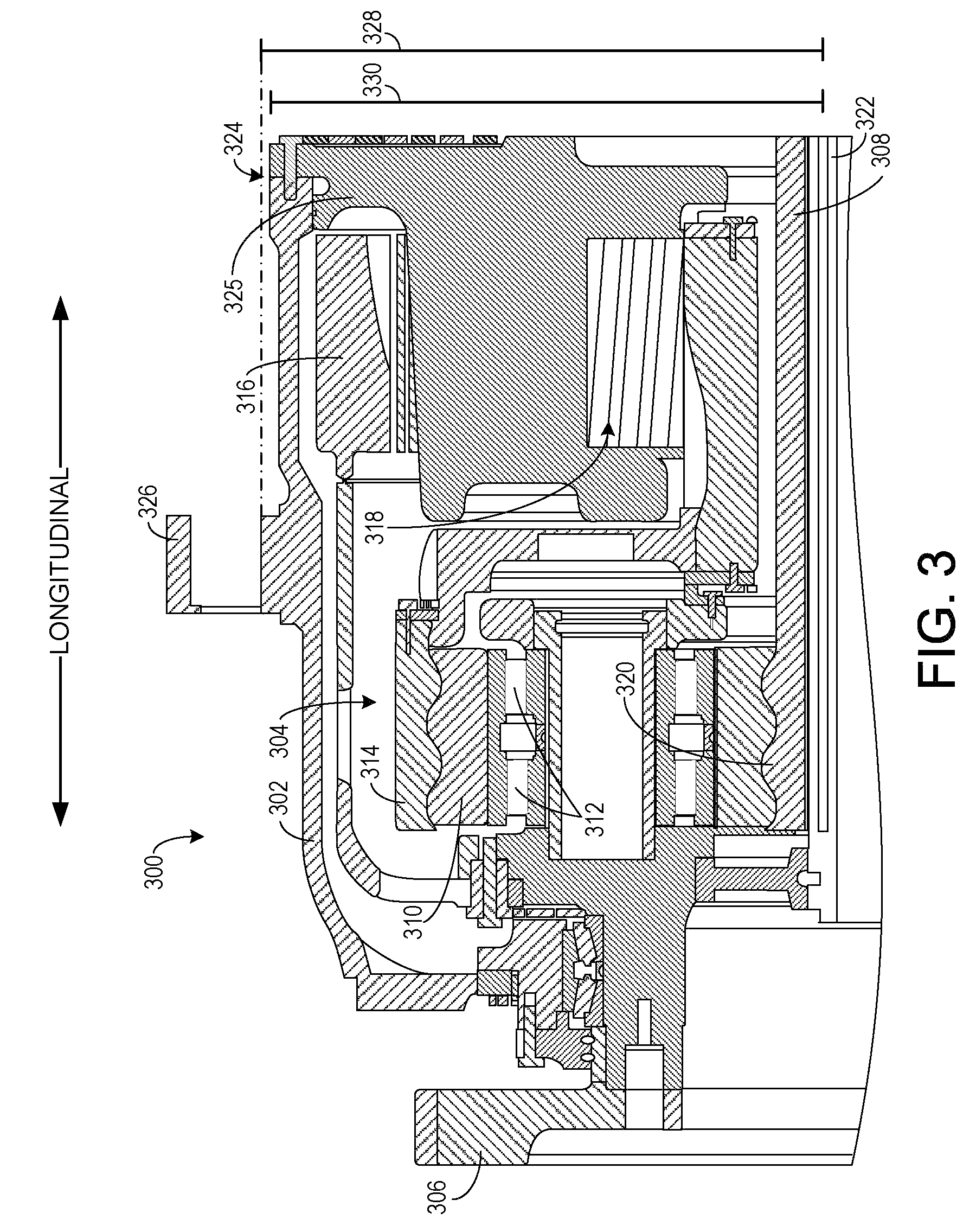
[0018]A transmission for a wind turbine is described herein. The transmission includes a torque reacting joint configured to react torque generated by the wind interacting with the turbine blades. The torque reacting joint may be configured to react a substantial amount of the wind-generated torque while maintaining a compact and efficient design using mating indents in a housing of the transmission. FIGS. 1-2 describe an example wind turbine operating environment in which the torque reacting joint may be used, although it may also be used in other power transmission applications. Further, various views illustrating example torque reacting joints are shown in FIGS. 3-11.

[0019]A power generating wind turbine 10 is shown in FIG. 1. The turbine includes a tower 12 extending substantially vertically out of a base 14. The tower may be constructed from a plurality of stacked components. However, it can be appreciated that alternate configurations of the tower are possible, such as a latti...


PUM


Abstract

A transmission, including a gear-train and an outer housing enclosing the gear-train, the outer housing including a torque reacting joint coupling a first section of the transmission to a second section of the outer housing, the torque reacting joint including mating indents between the first and second sections.

Description

CROSS REFERENCE TO RELATED APPLICATIONS[0001]The present application claims priority to U.S. Provisional Patent Application Ser. No. 61 / 079,743 entitled “Structural Joint for High Torque Transmission in a Wind Turbine Gearbox”, filed Jul. 10, 2008, the disclosure of which is hereby incorporated by reference.BACKGROUND[0002]The wind turbine industry has been experiencing unprecedented growth in recent years due to the demand for clean, renewable energy. Small and efficient design has been a central objective of the wind turbine industry to reduce the cost of the wind turbine and in some cases increase the turbine's efficiency. However, small and efficiently designed wind turbines may be difficult to achieve for a multitude of reasons.[0003]Wind turbines typically include a transmission, such as a gearbox, to transfer and adjust power from turbine blades to a generator. Specifically, the transmission adjusts the speed and the torque from the rotor blades, allowing energy to be efficie...

Claims


Application Information

Patent Timeline
Patent Type & Authority Patents(United States)
IPC IPC(8): F16H57/08
CPCF03D11/02F16H37/0833F16H57/031F16H57/082F05B2260/40311F16H2057/02078F16H2057/02086F16H2057/0222Y02E10/722Y02E10/725F03D15/00F03D15/10F03D80/70Y02E10/72
Inventor CISZAK, ROBERT JOHNMARSDEN, KEITHROY, DENNISOWENS, STEVEN
Owner GENERAL ELECTRIC CO
Why Eureka
Try Eureka