
Liquid crystal screen

Active Publication Date: 2012-10-16
INTERDIGITAL CE PATENT HLDG
View PDF12 Cites 0 Cited by
  • Summary
  • Abstract
  • Description
  • Claims
  • Application Information

AI Technical Summary

Benefits of technology

[0022]The subject of the invention is an LCD screen with a configuration of the optical film or films at the rear face of the polarizer which facilitates encapsulation with the sought-after qualities.
[0023]The object of the invention is to solve a technical encapsulation problem that may be formulated as follows: to propose an inexpensive rear encapsulation structure that is simple to implement, resistant to variations in atmospheric pressure and has no leaktightness problems for an LCD module comprising at least one optical film at the rear of the polarizer; a structure which can be used whatever the damp-environment storage qualities of the polarizer; a structure which can be altered, allowing the integration of other optical functionalities (DBEF, BEF, holographic diffuser, diffuser, etc.) at the rear of the cell while still complying with the conditions enumerated above.

Problems solved by technology

However, it exhibits various drawbacks:the VHB frame has a high manufacturing cost: indeed, the frame is made by removing the central material from a sheet of adhesive material: the whole of this central portion is lost.the VHB frame uses the peripheral edge 1a of the plate 1, outside of the active optical zone Z of the cell.
This is an inconvenient limitation since it is increasingly sought, even in constraining applications of avionics type, to use off-the-shelf components termed COTS, to reduce costs.
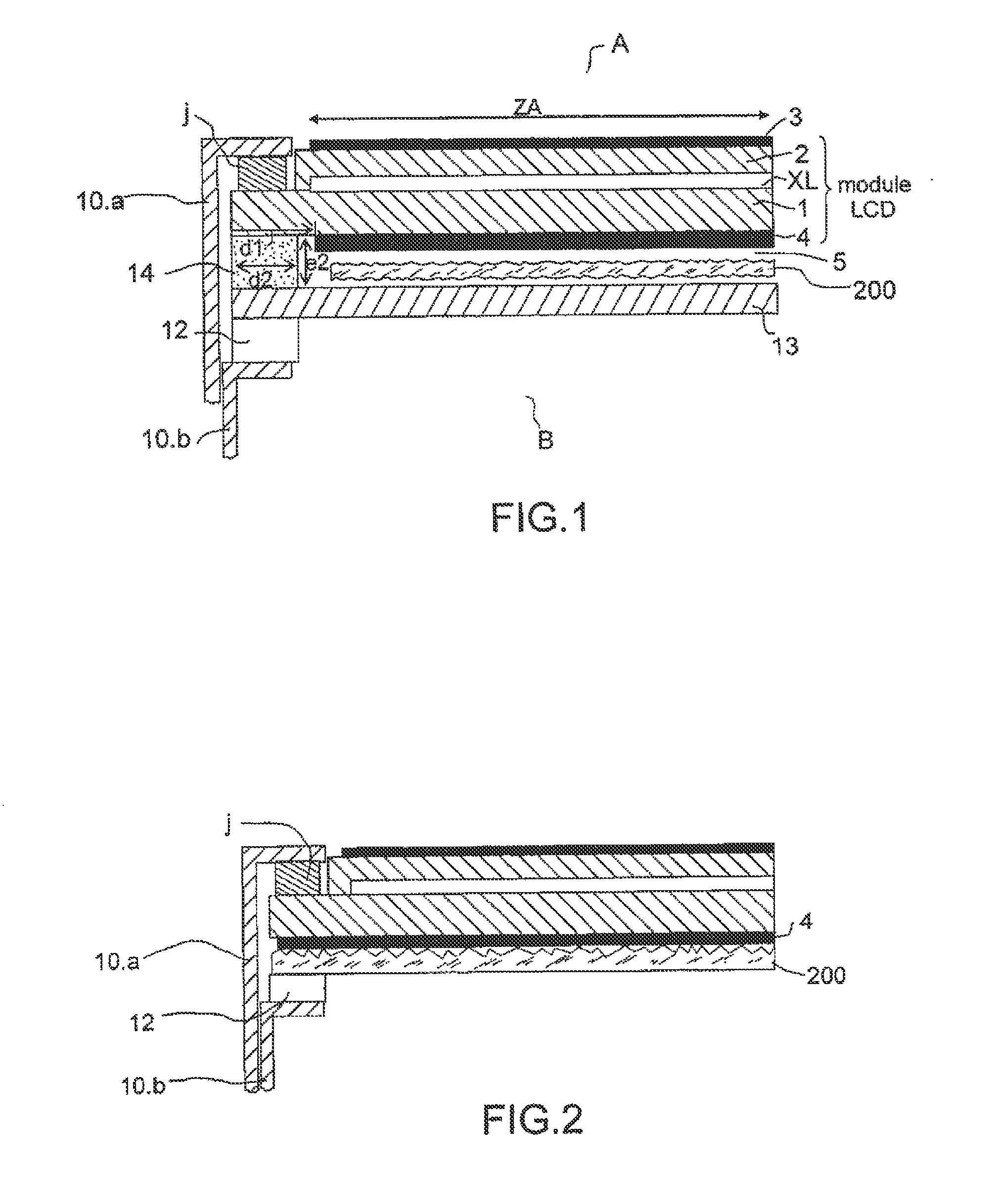
This sensitivity to pressure variation is very inconvenient for LCD screens dedicated to avionic applications, with risks either of opening during large pressure variations, or of bonding of smooth interfaces (rear shim with polarizer or DBEF, diffuser with rear shim, etc.)according to the screen's storage conditions, an optical film such as 200, placed at the rear of the cell in the space 5 between the two planes 4 and 12, may crinkle.
At the optical level, crinkling results in non-uniformities of the LCD back-lighting and therefore degraded image quality.repair, for example to replace the crinkled film, requires the dismantling of the mechanical structure.
However, as the polarizer exhibits a smooth rear surface, this can only be done by using an optical film exhibiting a nonzero surface roughness, as taught in the U.S. Pat. No. 4,508,428.
Otherwise, if the optical film also exhibits a smooth surface, the assemblage would introduce cosmetic defects such as interference or Newton's rings.
This liquid trapped at various places o1, o2 then gives rise to defects of non-uniformity of illumination.
Once trapped, the liquid cannot easily evaporate.
Even drying the screen may leave traces of dried water and / or water residues, which will have the same unacceptable optical effects.
More generally, as it may be beneficial to integrate several optical films at the rear, each ensuring a particular optical functionality, the problem of the leaktightness of the interface arises each time.
Finally, the replacement of an optical film exhibiting a defect necessarily requires the dismantling of the mechanical structure, which is not desirable.

Method used


Image

  • Liquid crystal screen
  • Liquid crystal screen
  • Liquid crystal screen

Examples


first embodiment

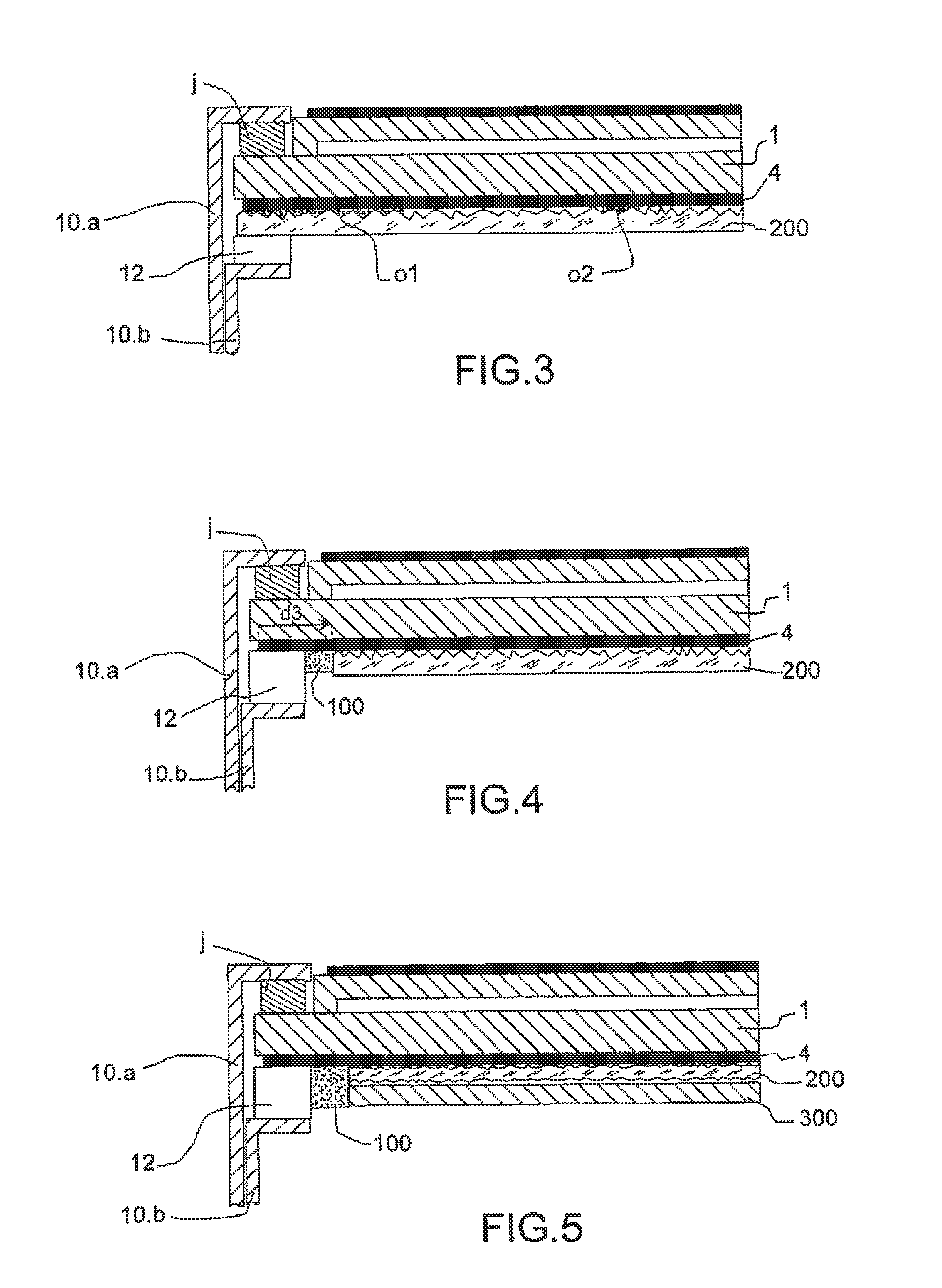
[0049]FIG. 4 illustrates an LCD screen comprising a diffuser optical film 200 at the rear of the LCD module, applicable in the case where the polarizer 4 at the rear of the LCD cell is of the type hardened to storage in a damp environment.

[0050]The polarizer 4 is dispensed over substantially the whole extent of the plate 1 of the cell. As indicated by way of preface, this is a pure polarizer or a polarizer combined with another optical function by lamination of an optical film, by means of a glue of suitable index (polarizer / DBEF for example). This known type of assemblage does not exhibit any leaktightness problem at the interface or at the rear of the film, or any optical interference problems.

[0051]The spacer 12 is overlaid against the rear polarizer 4, around the whole perimeter of the module.

[0052]The diffuser 200 is overlaid against the rear polarizer 4, but set back from the edge of the polarizer, by a distance d3, and set back from the spacer 12. It exhibits a rough surface ...

second embodiment

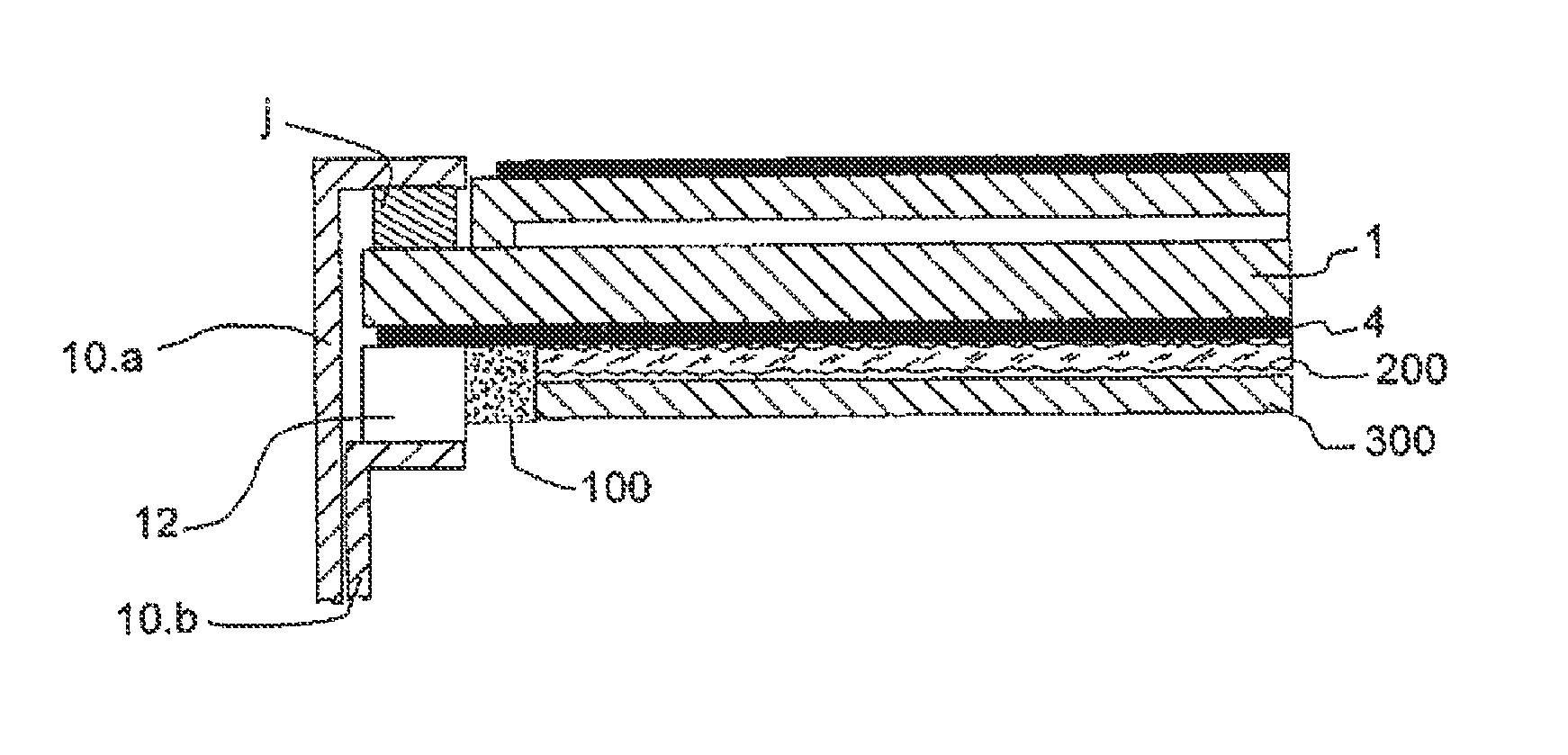
[0059]FIG. 5 illustrates the invention, which makes it possible advantageously to integrate a heater at the rear face, without being detrimental to the optical qualities of the screen. The stack comprises in the example an optical film 200, for example a diffuser, whose two faces are rough.

[0060]In a more detailed manner, the optical film 200 is then sandwiched between two smooth planes, that of the polarizer (or of the polarizer+a laminated DBEF film) and that of a transparent panel. This panel 300 can then advantageously be equipped with a heater, typically a heating resistor. The panel will for example be made of glass and more generally from a material which does not deteriorate with the temperature arising from the heater 300.

[0061]As in the embodiment of FIG. 4, the assembly comprising the optical stack comprising the diffuser 200, and the transparent panel 300, is made set back from the edge of the polarizer and the spacer.

[0062]The bead of glue is dispensed as previously ind...


PUM


Abstract

An LCD screen comprises an optical stack of at least one optical film against the rear polarizer placed at the rear of the plate of the LCD module. That face of the optical film overlaid against the polarizer is rough. A bead of glue is dispensed over the thickness of the rim of the stack over the whole of its perimeter. Depending on whether or not the polarizer is of the hardened type, the screen is encapsulated in a mechanical structure comprising an outer frame and an inner frame clamping the plate and the rear polarizer or the plate alone, the bead of glue being dispensed in the space between the inner frame and the stack.

Description

CROSS-REFERENCE TO RELATED APPLICATIONS[0001]This application is a National Stage of International patent application PCT / EP2008 / 064778, filed on Oct. 31, 2008, which claims priority to foreign French patent application No. FR 07 07675, filed on Oct. 31, 2007, the disclosures of which are incorporated by reference in their entirety.FIELD OF THE INVENTION[0002]The present invention relates to a liquid crystal screen and more particularly to the rear structure of this screen allowing improved encapsulation.BACKGROUND OF THE INVENTION[0003]Producers of LCD screens supply these screens to users who will integrate them into an end product, such as an instrument board or a portable device for example. The screens are supplied encapsulated in a rigid mechanical structure forming a frame.[0004]FIG. 1 illustrates an example of rear encapsulation of an LCD screen. The example represented corresponds to a basic configuration comprising a frame 10 clenching an LCD cell, that is to say a plate 1...

Claims


Application Information

Patent Timeline
IPC IPC(8): G02F1/1335
CPCG02F1/133308G02F1/133528G02F2001/133311G02F2202/28G02F1/133311
Inventor KRETZ, PRENOMS THIERRYMEUNIER, BERNARD
Owner INTERDIGITAL CE PATENT HLDG
Learn More