Line switcher for power converters

a technology of power converters and switchers, which is applied in the field of power supplies, can solve the problems of increasing the loss of converters, irreparable damage, and uncertain and undesirable functioning of circuits, and the cost of the main switching semiconductors of conventional ac to dc converters

Active Publication Date: 2012-10-16
FLEXTRONICS AP LLC
View PDF139 Cites 11 Cited by
  • Summary
  • Abstract
  • Description
  • Claims
  • Application Information

AI Technical Summary

Benefits of technology

[0009]The present invention uses thyristors and intelligent sensing and switching schemes to provide fast switching from low-line (85 VAC-132 VAC) to high-line (180 VAC-264 VAC). Rather than turning a single semiconductor switch on or off to enable a voltage doubler, the present invention turns several semiconductor switches on or off to place two half-sized converter input stages in series or parallel, depending on whether the line is low or high. The transformer isolation stage allows the converters to be placed in series or parallel on the primary-side of the transformer while the secondary-sides of the two converters can be appropriately connected, without regard for whether the primary-sides are in parallel or series. Converters with multiple outputs can be combined in much the same way as converters with a single output. The exact method of combining the secondary sides of the converters will depend on the type of converter and the design constraints.

Problems solved by technology

Some circuits are subject to uncertain and undesirable functioning and even irreparable damage if an input power supply falls outside a certain range.
The cost of the main switching semiconductors of conventional AC to DC converters and the losses in the converters increase dramatically with the range of input voltages supported by the converter.
Conventional low-power converters, typically less than 65 watts, usually do not have government requirements for a high power factor and typically operate with a low power factor.
This is inefficient and costly.
A disadvantage of the conventional line switcher 500 is that it draws a power with a poor power factor and is therefore only useful, in practice, for small converters such as those below 75 W. Another disadvantage of the conventional line switcher 500 is a reduced efficiency caused by the high pulsed currents used to charge the first and second large electrolytic capacitors C1, C2.

Method used


Image

  • Line switcher for power converters
  • Line switcher for power converters
  • Line switcher for power converters

Examples


Embodiment Construction

[0029]In the following description numerous details and alternatives are set forth for the purpose of explanation. However, one of ordinary skill in the art will realize that the invention can be practiced without the use of these specific details. In other instances, well-known structures and devices are shown in block diagram form in order not to obscure the description of the invention with unnecessary detail.

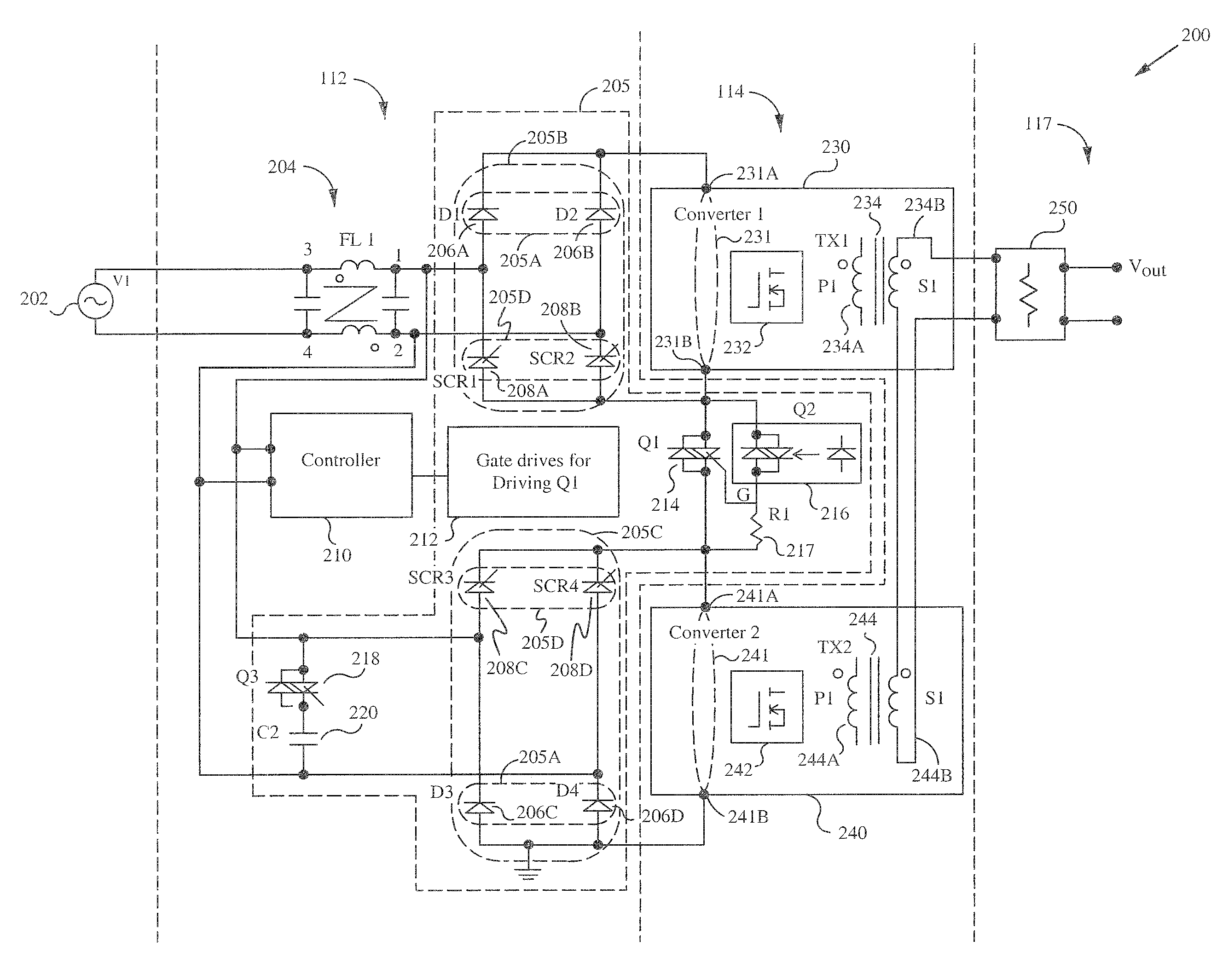
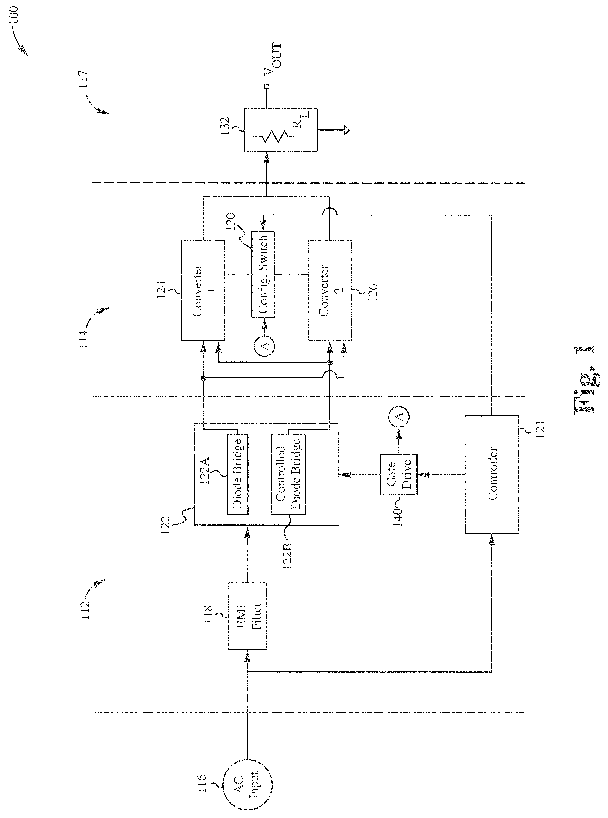
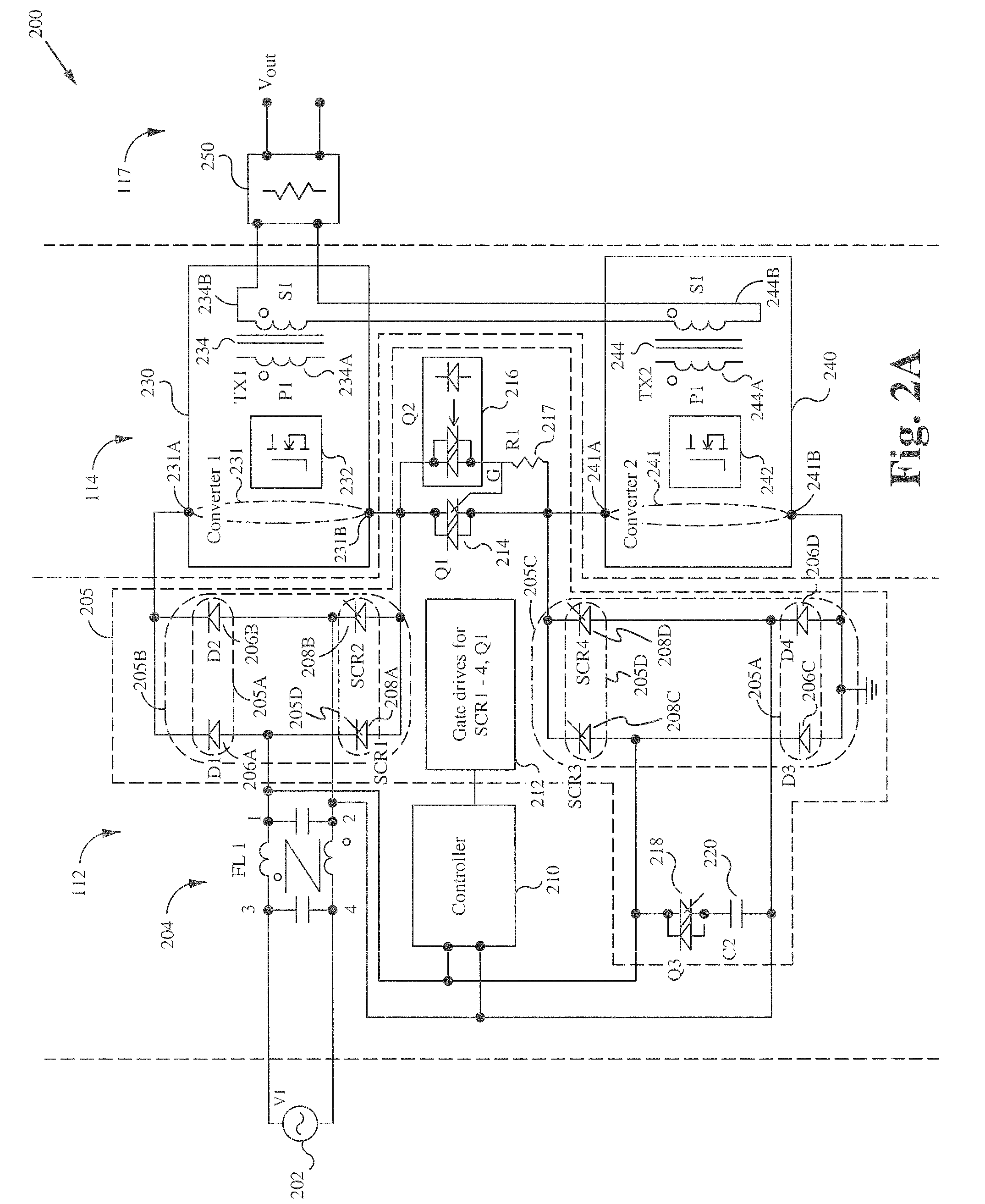
[0030]The present invention uses thyristors and intelligent sensing and switching schemes to provide fast switching from low-line (85 VAC-132 VAC) to high-line (180 VAC-264 VAC). The present invention takes advantage of the similar voltage drop between a diode and an SCR to provide a low-cost switcher which has an efficiency close to that of a traditional input rectifier. Although the cost of the thyristors is higher than that of a diode, the additional costs are offset by the costs of designing a wide-input-voltage-range converter above a nominal power level. For example, a...


PUM


Abstract

A regulated power supply apparatus and method are provided. The apparatus includes a converter circuit for generating a regulated voltage signal. The converter circuit includes a first switching circuit and a second switching circuit both coupled with an output circuit. A first and a second transformer include a first and a second secondary, which are coupled with each other in series or alternatively, coupled with each other in parallel. An input rectifier circuit is coupled with the first and the second switching circuit. The input rectifier circuit is configured for receiving an AC input voltage and for generating a rectified voltage. The input rectifier circuit includes controlled switches and a first and second configuration of a bridge rectifier that couples the first and second switching circuits in series or parallel depending if the AC input power signal is “high-line” or “low-line.” A controller circuit is provided for enabling either the first configuration or the second configuration. A configuration switch is controlled by the controller circuit for coupling the first and second switching circuits together.

Description

FIELD OF THE INVENTION[0001]The present invention relates to the field of power supplies. More particularly, the present invention relates to a line switcher circuit for a power supply apparatus.BACKGROUND[0002]In many applications a voltage regulator is required to provide a voltage within a predetermined range. Some circuits are subject to uncertain and undesirable functioning and even irreparable damage if an input power supply falls outside a certain range.[0003]AC to DC converters are typically designed to operate over a wide voltage range such as 90 VAC to 264 VAC so that the converters can operate with AC line voltages from anywhere in the world. In practice, the AC line voltages encountered throughout the world lie within the ranges 90 VAC-132 VAC for “low-line” operation and 180 VAC to 264 VAC for “high-line” operation. The cost of the main switching semiconductors of conventional AC to DC converters and the losses in the converters increase dramatically with the range of i...

Claims


Application Information

Patent Timeline
Patent Type & Authority Patents(United States)
IPC IPC(8): H02M7/08
CPCH02M7/219H02M1/0085
Inventor JUNGREIS, AARON
Owner FLEXTRONICS AP LLC
Why Eureka
Try Eureka