
Time shifted harmonics generator

a harmonic generator and time-shifted technology, applied in the field of electro-processed sound, can solve problems such as reducing the audibility of the effect, and achieve the effect of increasing the perceived effect of harmonics and the peak level of transients

Active Publication Date: 2012-10-16
FREEDMAN ELECTRONICS
View PDF3 Cites 3 Cited by
  • Summary
  • Abstract
  • Description
  • Claims
  • Application Information

AI Technical Summary

Benefits of technology

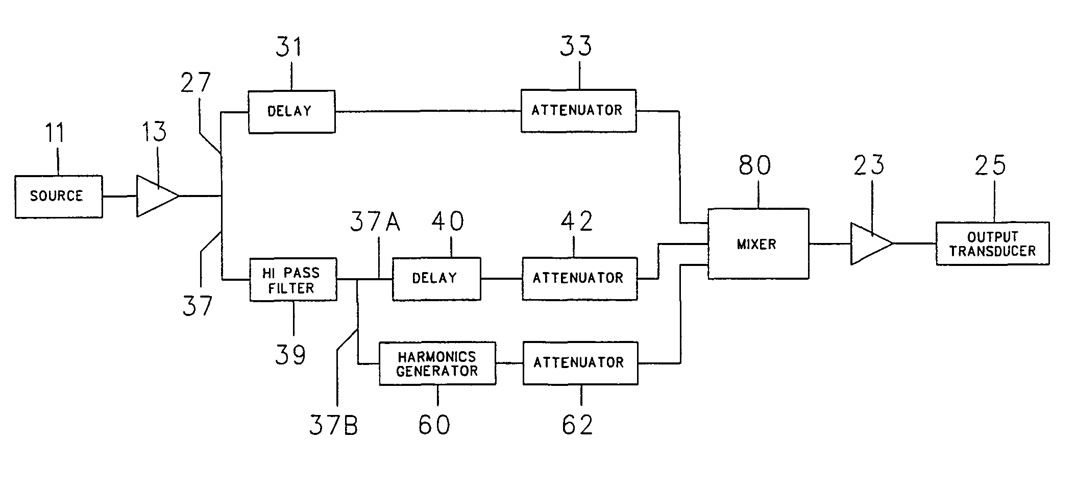
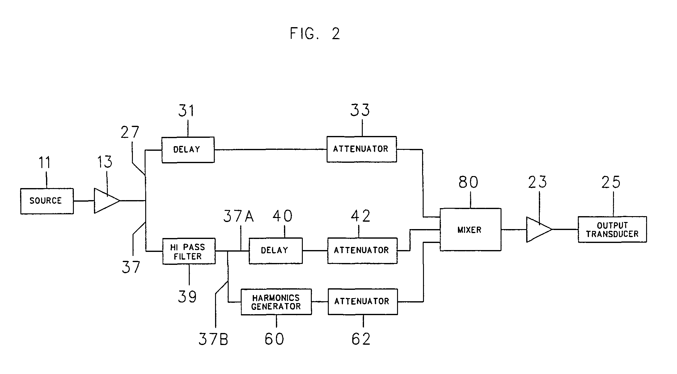
[0008]It has been discovered that the use of a delay on both the input signal and the portion of the signal which passed through the high pass filter output just before the summing amplifier enables the harmonics generated by the harmonics generator after the signal passed through the high pass filter to be advanced in time ahead of the input and high pass filter signals. As a result, the harmonics are not masked by the lower frequencies, making the effect more apparent. In addition, the peak level of the transient is increased less because the added harmonics are ahead in time of the transient that generated the harmonics.

Problems solved by technology

A problem with the prior art references discussed above is that the harmonics are masked by the lower frequencies, thereby reducing the audibility of the effect.

Method used


Image

  • Time shifted harmonics generator
  • Time shifted harmonics generator
  • Time shifted harmonics generator

Examples


Embodiment Construction

[0015]Although specific embodiments of the present invention will now be described with reference to the drawings, it should be understood that such embodiments are by way of example only and merely illustrative of but a small number of the many possible specific embodiments which can represent applications of the principles of the present invention. Various changes and modifications obvious to one skilled in the art to which the present invention pertains are deemed to be within the spirit, scope and contemplation of the present invention.

[0016]Referring to FIG. 2 there is illustrated a block diagram of the present invention. An electrical signal 11 derived from an audio source such as a microphone, radio tuner, amplifier, etc. is passed through an amplifier 13 and is then divided into two discrete signal paths 27 and 37. The signal traveling along the first path 37 is passed through a high pass filter circuit 39. The signal is then split. A first portion 37A of the signal 37 passe...


PUM


Abstract

An electrical signal derived from an audio source is passed through an amplifier and is then divided into two discrete signal paths. The signal traveling along the first path travels through a high pass filter and is then split so that a portion is delayed and a portion passes through a harmonics generator so that the harmonics are advanced ahead of the delayed portion from the high pass filter. The split circuit is then combined in a summing amplifier. The second portion of the signal is also delayed before it also travels to the mixer. The combined signal is passed through an amplifier and then fed into an output transducer. The use of a delay both on the input signal and the portion of the signal which passed through the high pass filter output just before the summing amplifier enables the harmonics to not be masked by the lower frequencies, making the effect more apparent.

Description

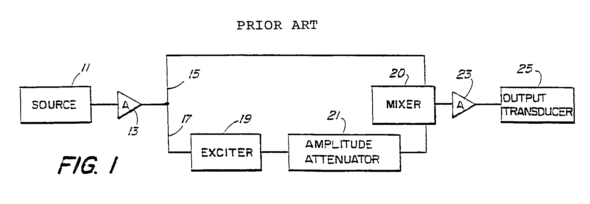
BACKGROUND OF THE INVENTION[0001]1. Field of the Invention[0002]The present invention relates to electronically processed sound to enhance the quality, clarity, presence, intelligibility and other characteristics of electronically processed sound.[0003]2. Description of the Prior Art[0004]In general, the concept of electronically processed sound to enhance the quality, clarity, presence, intelligibility and other characteristics of analog electronically processed sound is known. U.S. Pat. No. 4,150,253 to Knoppel addressees the concept. As set forth in FIG. 1 taken from this patent, the sound source 11 passes through an amplifier 13 and then divided into two discrete signal paths 15 and 17. The signal traveling along path 17 is passed in succession through an exciter circuit 19 and amplitude attenuator 21 and is then combined in a mixer 20 traveling along path 15. The combined signal is passed through an amplifier 23 and then fed into an output transducer 25 such as a loudspeaker. T...

Claims


Application Information

Patent Timeline
Patent Type & Authority Patents(United States)
IPC IPC(8): H03G3/00H04R5/00H03G5/00H04B1/00
CPCH03G5/18H04R3/00G10L21/0364
Inventor CAESAR, MARVIN W.
Owner FREEDMAN ELECTRONICS
Learn More