Method, bus components, and control system for ethernet-based control of an automation system

a technology of automation system and control system, applied in the field of automation system, can solve the problems of unnecessarily high cost, inability to physically control the node, inefficient ethernet protocol, etc., and achieve the effect of improving the control of automation system

Active Publication Date: 2012-10-16
PHOENIX CONTACT GMBH & CO KG
View PDF12 Cites 11 Cited by
  • Summary
  • Abstract
  • Description
  • Claims
  • Application Information

AI Technical Summary

Benefits of technology

[0006]The invention is therefore based on the problem of disclosing a way of improving the control of automation systems, especially in real time, incorporating an Ethernet-based network, so that the disadvantages described above can be avoided.
[0007]Another problem of the invention is to disclose a means of providing and operating, in the most efficient way possible, a real-time-capable Ethernet-based control system with a plurality of nodes and, simultaneously, low costs for each node.
[0017]Furthermore, management data for controlling at least one bus node of the lower-level bus system can be advantageously generated by the bus coupler and inserted into the internal data telegram without disrupting the time response of the data transfer between a control unit connected to the Ethernet-based network and the bus nodes of the lower-level bus system.
[0018]Advantageously, because an internal data telegram, reduced in length compared with the Ethernet telegram, is circulated over the ring-shaped, lower-level bus system instead of an Ethernet telegram, in an especially advantageous way, a higher data transfer rate to the bus nodes of the lower-level bus system is achieved, wherein stricter real-time requirements can be maintained.
[0020]In order to prevent or at least reduce the remaining jitter, the invention provides, in an especially advantageous way, for the bus nodes of the lower-level bus system to be formed such that the LatchIN and LatchOUT times of the bus nodes can be parameterized. The LatchOUT time here designates the time at which data is output to the process by the appropriate bus node, and the LatchIN time designates the time at which new data is read in from the peripheral, for example, a sensor, through the bus node.

Problems solved by technology

If many field devices that require only very little user data are used in an Ethernet-based system, the Ethernet protocol is very inefficient and makes the system slow.
Another disadvantage of an Ethernet-based field-bus system is the requirement that each node must be physically equipped with an Ethernet interface, despite the fact that often only small distances must be bridged.
This leads to unnecessarily high costs.
Another disadvantage of the Ethernet interface is that the conversion into digital signals generates a not-insignificant delay, which must be taken into consideration when there are many nodes in a system.
Therefore, Ethernet-based field-bus systems can be used only to a limited extent for real-time applications in the field of automation systems.
However, one disadvantage of the method described in EP 1 590 927 B1 is that the Ethernet telegram circulating on the ring-shaped transmission path has at least 72 bytes and thus features the overhead to the data described above.
Furthermore, the use of the ring-shaped transmission path leads to jitter that limits the ability to maintain real-time requirements.

Method used


Image

  • Method, bus components, and control system for ethernet-based control of an automation system
  • Method, bus components, and control system for ethernet-based control of an automation system
  • Method, bus components, and control system for ethernet-based control of an automation system

Examples


Embodiment Construction

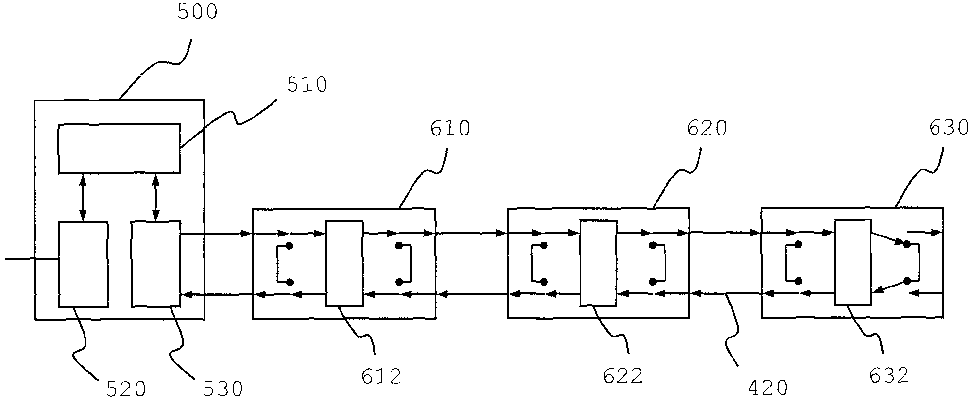
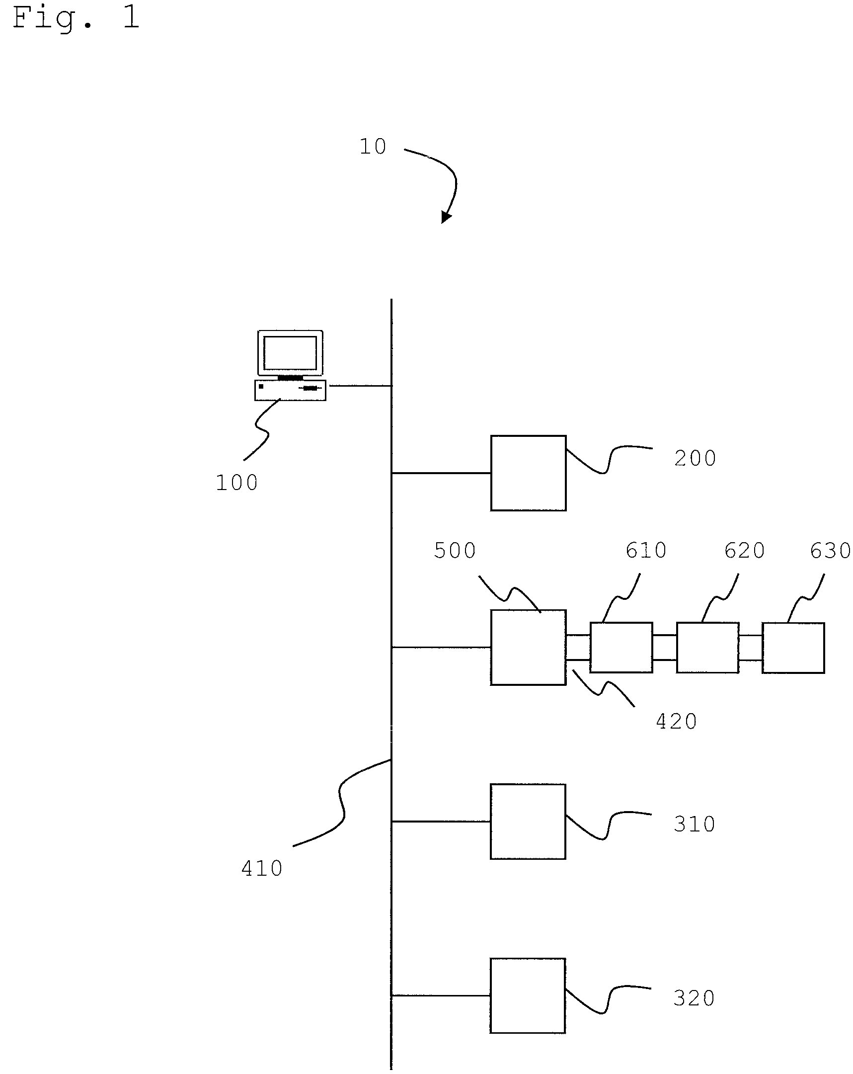
[0041]A control system 10 according to the invention formed for executing a method according to the invention is shown in FIG. 1. For controlling an automation system, the devices 100, 200, 310, 320, and 500 equipped with an Ethernet interface are connected to a network 410 formed for transmitting Ethernet telegrams. The network 410 is advantageously formed as a Profinet to which are connected, in the shown embodiment, a personal computer 100 for the configuration and visualization of the control process, a control unit 200 for the control of the process, and also, as an example, additional Ethernet-capable field devices 310 and 320. Furthermore, a bus coupler 500 for data exchange with a lower-level bus system 420 is connected to the network 410. In order to keep the cabling expense low, the devices connected to the network 410 are advantageously connected in series. The network 410, however, can also have any other suitable topology.

[0042]The invention provides for use of a common...


PUM


Abstract

A method is disclosed in which data is exchanged via a bus coupler (500) between a network (410) designed for transmitting Ethernet telegrams and a lower-level bus system (420), wherein the bus coupler (500) is connected via a first interface (520) to the network (410) and via a second interface (530) to the lower-level bus system (420), and wherein process data is read in and / or output through at least one bus node (610, 620, 630) of the lower-level bus system (420).Furthermore, a bus coupler (500), a bus node (610, 620, 630), and a control system (10) that are designed for execution of the method are disclosed.

Description

FIELD OF THE INVENTION[0001]The invention relates, in general, to automation systems and, in particular, to a method, a bus coupler, a bus node, and a control system for real-time control of an automation system.BACKGROUND OF THE INVENTION[0002]In automation systems, Ethernet-based field-bus systems are being used more and more. Based on the Ethernet protocol, these systems use an Ethernet data frame for responding to a connected device. However, an Ethernet data frame features not-insignificant overhead to the data, so that, for example, a simple digital field device with, for example, only 8 digital outputs must receive a data frame that is composed of at least 72 bytes. If many field devices that require only very little user data are used in an Ethernet-based system, the Ethernet protocol is very inefficient and makes the system slow.[0003]Another disadvantage of an Ethernet-based field-bus system is the requirement that each node must be physically equipped with an Ethernet int...

Claims


Application Information

Patent Timeline
Patent Type & Authority Patents(United States)
IPC IPC(8): G06F13/42
CPCG05B19/042H04L12/24H04L12/4625H04L41/00G05B2219/25012G05B2219/25174H04L2012/4026H04L2012/40221H04L12/40006
Inventor KUSCHKE, DETLEVHOFFMANN, MICHAEL
Owner PHOENIX CONTACT GMBH & CO KG
Why Eureka
Try Eureka