Electric pressure execute shoring method and precision electric support thereof
A support method and support cylinder technology, which is applied in the direction of non-electric variable control, position/direction control, lifting device, etc., can solve the problems of complex oil circuit structure, poor control accuracy, and high production cost, so as to reduce production cost and precisely control Easy and convenient effect
- Summary
- Abstract
- Description
- Claims
- Application Information
AI Technical Summary
Problems solved by technology
Method used
Image
Examples
Embodiment 1
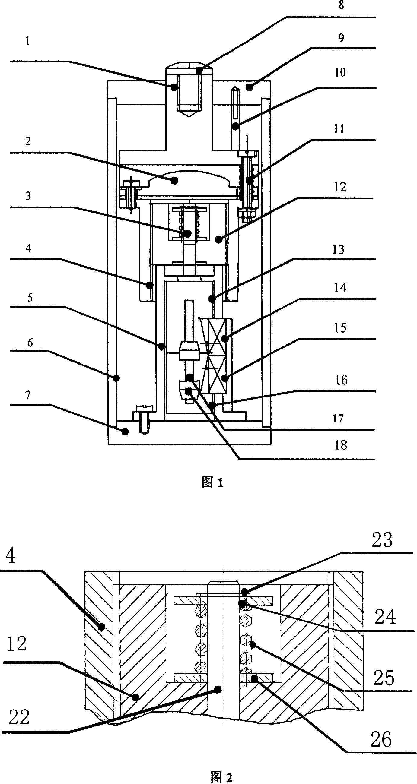
[0018] As shown in Figure 1, the support cylinder body 6 is a cylindrical structure, and its upper and lower ends are respectively provided with a top cover 9 and a base 7. The center of the top cover 9 is provided with a central hole, and the support rod 1 is sleeved on the body 6 The bobbin can move up and down, and its upper end is a support head 8 extending from the center hole of the top cover 9 for contact with the workpiece. The base 7 is fixed with a reducer bracket 5, and the reducer bracket 5 is equipped with a DC motor 16, DC The motor 16 and the reducer 13 are assembled in a shaft type. The output shaft end of the reducer 13 is equipped with a hollow thread head 12 to form a linkage mechanism. The thread head 12 and the nut 4 of the jacket form a thread pair that can move up and down. The upper end of 4 is fixedly connected with the switch contact 2 through the insulating pad to form the switch of the control circuit of the DC motor 16. The electrode positioning screw ...
Embodiment 2
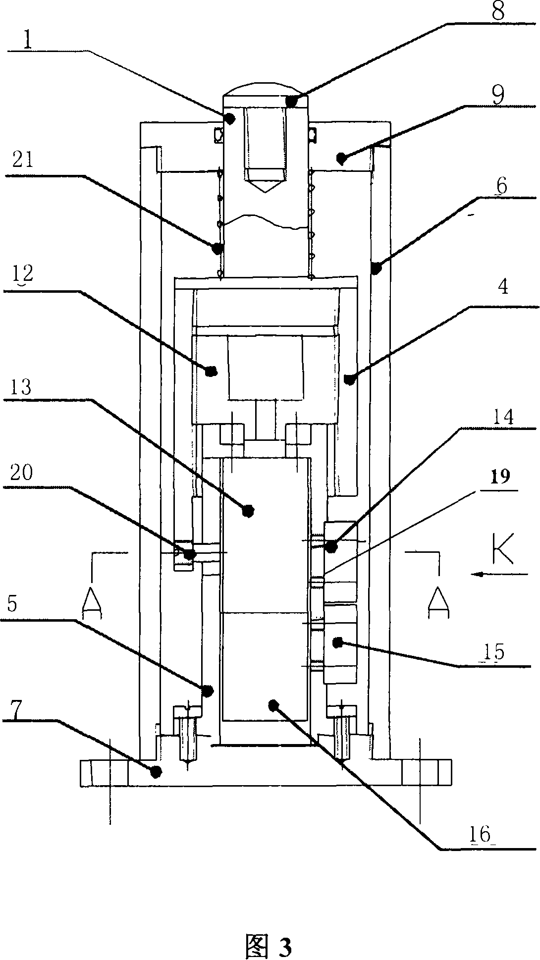
[0024] According to Fig. 3, the precision electric control stroke support cylinder is assembled with a shaft combination of the motor 16 and the reducer 13, and the output shaft end of the reducer 13 is equipped with a wire end 12. During operation, the motor 16 drives the speed reducer 13 to rotate, thereby driving the thread head 12 to rotate. The thread head 12 drives the thread mother 4 to move up and down according to the guide pin 20. That is, screw drive. The upper end of the nut 4 is equipped with a support rod 1, and drives the support rod 1 and the sliding rheostat 19 to move up and down. The sliding rheostat 19 is installed on the lower eaves of the nut 4, the reducer seat 5 is processed with a horizontal groove, and the sliding head of the sliding rheostat 19 is inserted. In the horizontal groove. When the nut 4 is raised and lowered, the horizontal groove moves the sliding head, and the resistance value of the sliding rheostat 19 changes accordingly. The control circu...
Embodiment 3
[0030]This system can also use the form of current overload to control the rise of the support rod. The specific working principle is: the motor 16 moves, and when the support head 8 at the upper end of the support rod 1 contacts the workpiece, the load of the motor 16 increases, and the current of the motor 16 When the current reaches the set value, the control circuit is turned on, the motor 16 is powered off, and the components stop moving, that is, the start and stop of the motor are controlled by collecting the change of the motor current.
PUM
 Abstract
Description
Claims
Application Information
 - R&D
- Intellectual Property
- Life Sciences
- Materials
- Tech Scout
- Unparalleled Data Quality
- Higher Quality Content
- 60% Fewer Hallucinations
Browse by: Latest US Patents, China's latest patents, Technical Efficacy Thesaurus, Application Domain, Technology Topic, Popular Technical Reports.
© 2025 PatSnap. All rights reserved.Legal|Privacy policy|Modern Slavery Act Transparency Statement|Sitemap|About US| Contact US: help@patsnap.com


