Method and apparatus for in situ unbalance and corrective balance determination for a non-vertical axis rotating assembly

a non-vertical axis rotating assembly and in situ unbalance technology, applied in adaptive control, computer control, instruments, etc., can solve the problems of increasing the necessary wind speed for power generation, reducing the mechanical life of connected components, and time-consuming methods

Inactive Publication Date: 2012-10-23
LENZ MICHAEL A W
View PDF30 Cites 9 Cited by
  • Summary
  • Abstract
  • Description
  • Claims
  • Application Information

AI Technical Summary

Benefits of technology

[0013]It is yet another object of the invention to provide a method and apparatus to determine the a prescriptive corrective balance solution which is independent of the vibratory response which eliminates the trial and error method of discovering a corrective solution and can be applied to both variable speed as well as constant speed rotating assemblies.

Problems solved by technology

In wind turbines, the increase in the degree of unbalance not only decreases the mechanical life of connected components but will also increase the necessary wind velocity required for the generation of power.
The method is time consuming and also extremely subject to environmental influences such as wind which will thereby affect the accuracy of the results.

Method used


Image

  • Method and apparatus for in situ unbalance and corrective balance determination for a non-vertical axis rotating assembly
  • Method and apparatus for in situ unbalance and corrective balance determination for a non-vertical axis rotating assembly
  • Method and apparatus for in situ unbalance and corrective balance determination for a non-vertical axis rotating assembly

Examples


Embodiment Construction

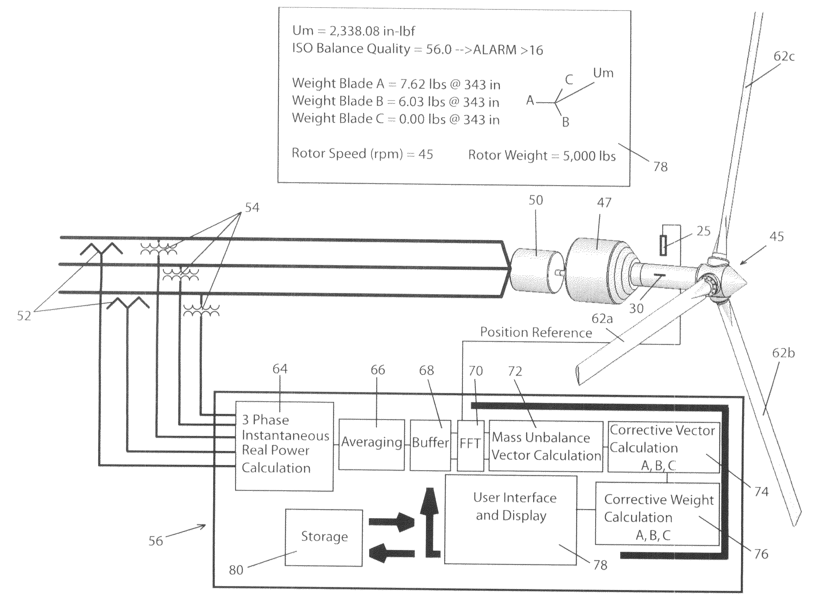
FIG. 1, 1a Preferred Embodiment

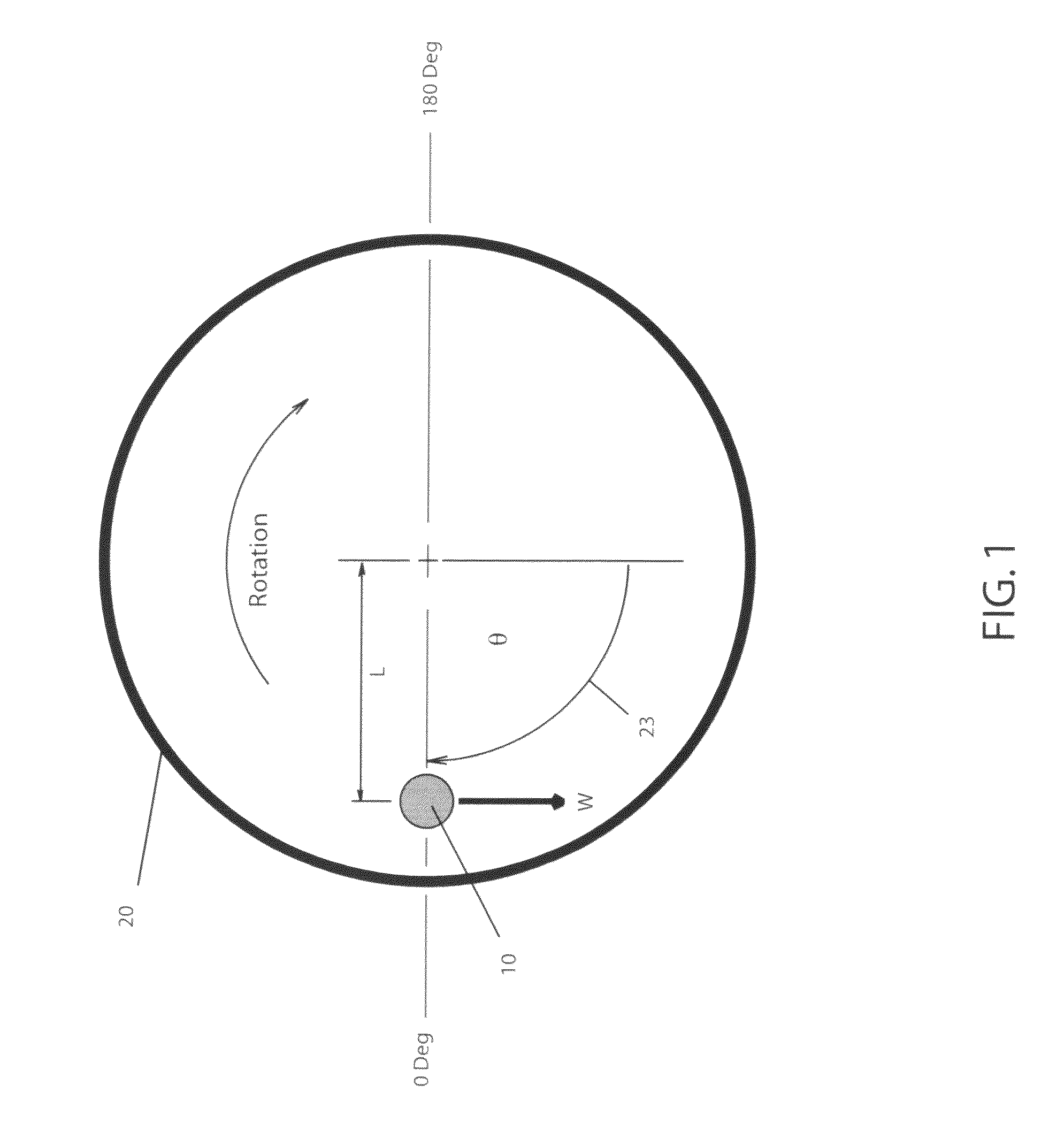
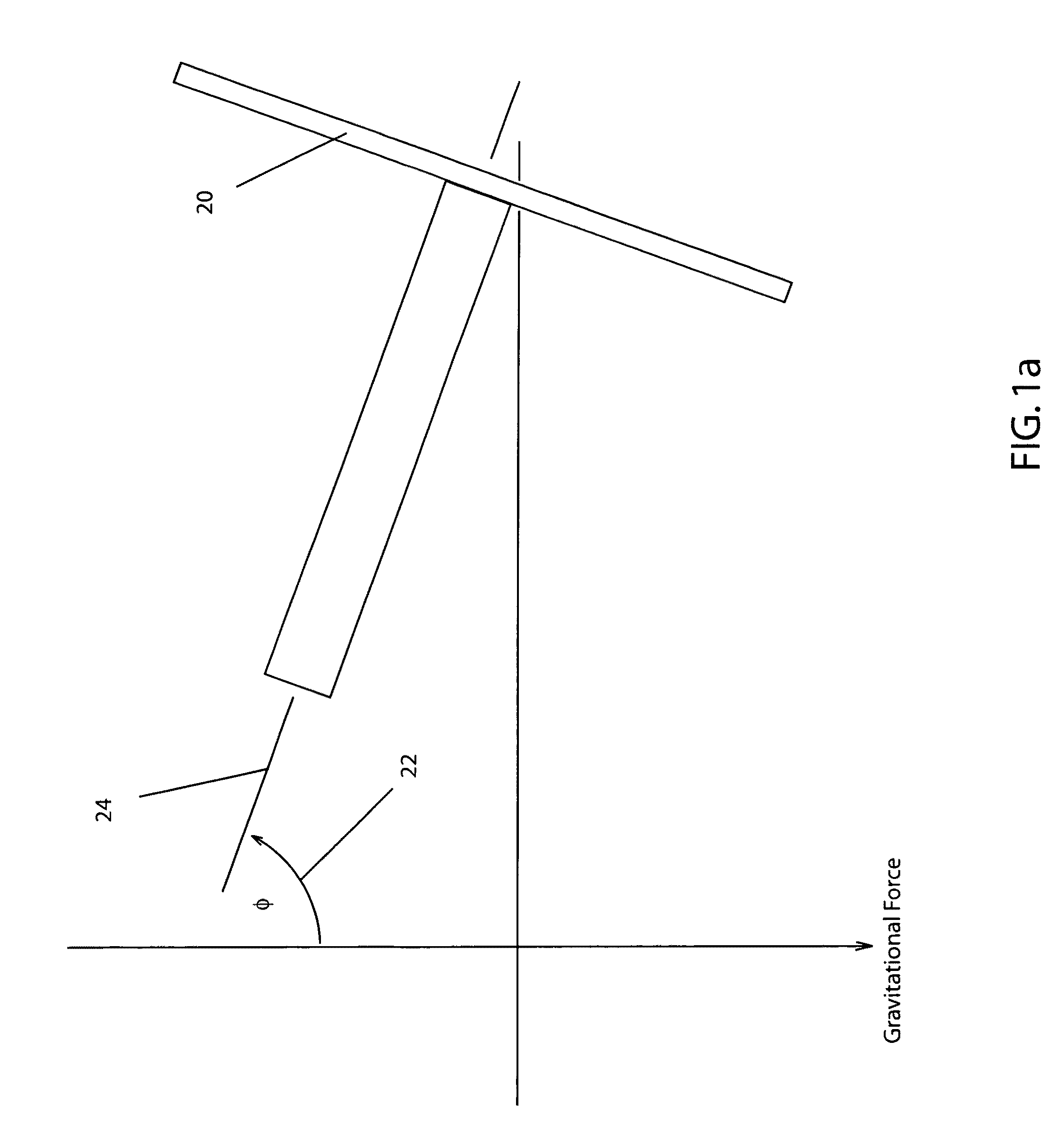
[0054]In order to appreciate the method disclosed, one must first understand basis upon which the objects of the invention can be realized. FIG. 1 is a free body force diagram which illustrates the static forces due to the center of mass not concentric to the axis of rotation. The center of mass may be represented by a mass 10 displaced at distance L from the axis of rotation on a disk 20 with an axis of rotation 24 having an axial angle of displacement 22 of 90 degrees relative to the force of gravity. The torque applied to axis of rotation 24 necessary to maintain equilibrium at any axial angle of displacement 22 and any rotational angle of displacement 23 is expressed by:

T=W*L*cos(θ)*sin(Φ),[0055]where[0056]Φ=axial angle of displacement 22 from gravitational force,[0057]θ=rotational angle of displacement 23 from a reference where a zero value of θ and the cos(θ) is positively maximum,[0058]L=distance of the Mass from the axis of rotation,[0059]*=mul...


PUM


Abstract

The invention discloses a novel method and apparatus to determine the degree of residual mass unbalance and a corrective balance solution for a rotating assembly having a non-vertical axis of rotation. When the center of mass of the rotating assembly is not concentric with the axis of rotation, the condition of unbalance exists. When the rotating assembly is driven by a motor or drives a generator, fluctuations in power are produced proportional to the degree of unbalance. The method and apparatus to determine the degree of mass imbalance consists of measuring the average instantaneous real power over an interval of time, calculating the Fourier Transform of the demodulated signal, establishing the peak amplitude and phase associated with the angular velocity of the rotating assembly and calculating the amount of unbalance. The method and apparatus to provide for a corrective solution consists of simultaneously acquiring a position reference signal of the rotating assembly with the average instantaneous real power signal, calculating the phase difference between the two acquired signals at the angular velocity of the rotating assembly, calculating the magnitude of the unbalance, and calculating the quantity and location of corrective weight necessary to minimize the unbalance to an acceptable level.

Description

CROSS REFERENCE TO RELATED APPLICATIONS[0001]Not applicable.STATEMENT REGARDING FEDERALLY SPONSORED RESEARCH AND DEVELOPMENT[0002]Not applicableBACKGROUND OF INVENTION[0003]1. Field of Invention[0004]This invention relates to the determination of the degree of unbalance and the balancing of a rotating assembly such that the vibratory effect of having the center of rotating mass eccentric to the axis of rotation is minimized.[0005]2. Related Art[0006]It is necessary that the center of mass of rotating assembles are concentric with the axis of rotation for optimal performance of their respective functions. Any deviation from this concentricity will represent additional forces which must be borne by a given structure that supports the rotating assembly. These additional forces manifest themselves as vibration and can not only interfere or diminish the ability of the rotating object to perform its function but can also accelerate the fatigue life of all the interconnected components the...

Claims


Application Information

Patent Timeline
Patent Type & Authority Patents(United States)
IPC IPC(8): G01M1/00
CPCG01M1/16
Inventor LENZ, MICHAEL A. W.
Owner LENZ MICHAEL A W
Why Eureka
Try Eureka