
Gradation correction apparatus and gradation correction method

a technology of gradation correction and apparatus, applied in the direction of image enhancement, visual presentation, color signal processing circuit, etc., can solve the problems of visual recognition of dither patterns on display screens, limit to the gradation which can be displayed, etc., to achieve the effect of reducing the diffusion range, reducing the performance of halftone processing, and reducing the gradien

Inactive Publication Date: 2006-06-01
KK TOSHIBA
View PDF4 Cites 6 Cited by
  • Summary
  • Abstract
  • Description
  • Claims
  • Application Information

AI Technical Summary

Benefits of technology

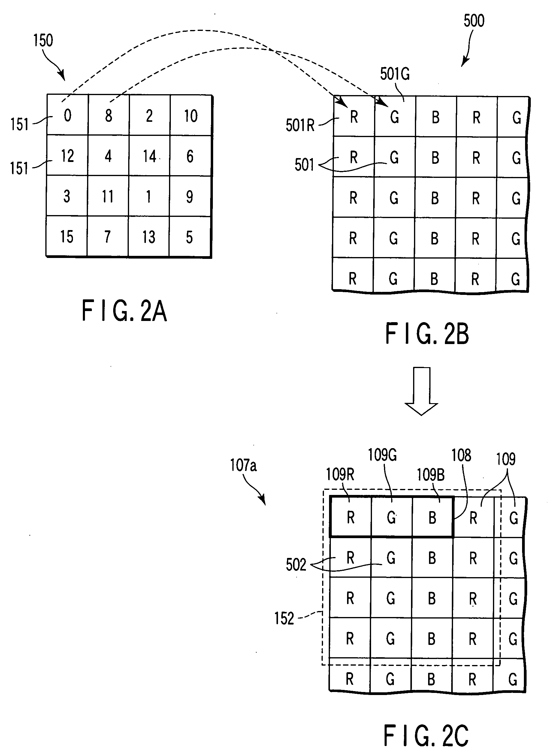
[0011] Then, in the present embodiment, halftone processing which is carried out in units of a pixel in the conventional art is carried out in units of each display element of R, G, B serving as a minimum unit for processing. In this manner, for example, in a case of a dither method, a region size on a display screen to which one dither pattern is applied can be made significantly smaller than that in the conventional method. Thus, it is possible to minutely control the gradient, and the performance of halftone processing can be improved. In a case of an error diffusion method as well, since the diffusion range is made significantly smaller even if an error is diffused in the same way as in the conventional method, the effect of halftone processing can be improved. Namely, the quality in a halftone display by using a dither method or an error diffusion method is improved.

Problems solved by technology

In a digital image display device such as a PDP (plasma display) or an LCD (liquid crystal panel display), there is a limit to the gradations which can be displayed.
The larger the region size to which the dither pattern is applied is, the easier the dither pattern can be visually recognized on the display screen, which is undesirable.
The larger the diffusion region size is, the easier the diffusion region can be visually recognized on the display screen, which is undesirable.

Method used


Image

  • Gradation correction apparatus and gradation correction method
  • Gradation correction apparatus and gradation correction method
  • Gradation correction apparatus and gradation correction method

Examples


first embodiment

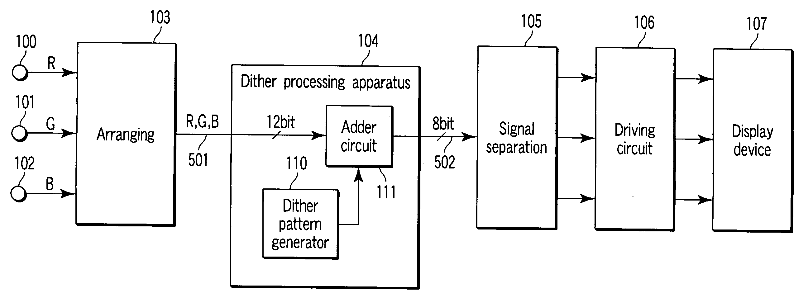
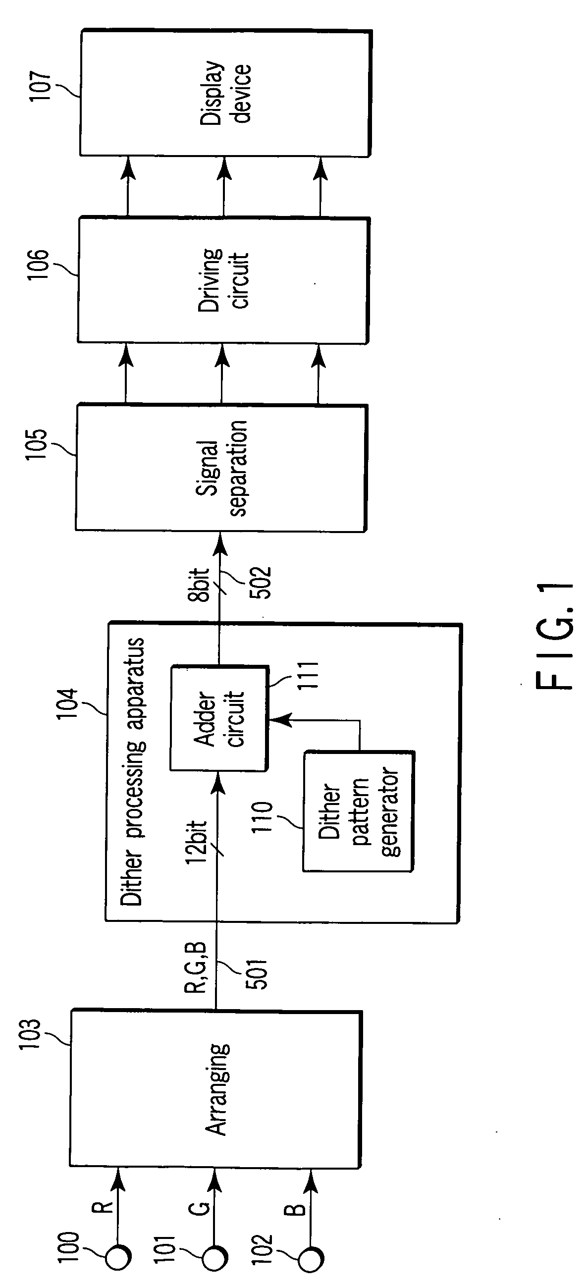
[0023]FIG. 1 is a block diagram showing a first embodiment of a gradation correction apparatus according to the present invention.

[0024] Terminals 100 to 102 are signal input parts into which signals of R (red), G (green), and B (blue) to be displayed on a display device are inputted in parallel. The signals of R, G, and B inputted from these terminals are inputted to an arranging circuit 103. The arranging circuit 103 arranges the input three signals into an arrangement which is the same as the arrangement of display elements of a display device 107, and outputs the R, G, and B signals (image data 501) in order. For example, when the display elements of the display device are arranged from the left to the right in the order of R, G, and B . . . , the image data 501 are outputted in the order of R, G, and B . . . in the same way. The image data 501 outputted from the arranging circuit 103 are inputted to a dither processing apparatus 104.

[0025] The dither processing apparatus 104 ...

second embodiment

[0041] A second embodiment of the present invention will be described in FIG. 5. Portions which are the same as those in FIG. 1 are denoted by the same numbers, and descriptions thereof will be omitted.

[0042] In the first embodiment, three signals are arranged, and the processing is carried out with respect to each of the signals in order. However, in the present embodiment, arranging is not carried out, and the three signals are processed simultaneously (in parallel).

[0043] The signals inputted in parallel from terminals 100 to 102 are respectively supplied to input terminals at sides of adder circuits 120 to 122. A dither pattern generator 123 generates dither pattern data. Pattern data outputted from the dither pattern generator 123 are inputted to input terminals at the other sides of the respective adder circuits 120 to 122.

[0044] The pattern data outputted from the dither pattern generator 123 are continuous values on a dither pattern which are different from one another. F...

third embodiment

[0048] A third embodiment is shown in FIG. 6. Components which are the same as those in FIG. 1 are denoted by the same numbers, and description thereof will be omitted.

[0049] The present embodiment is an example in which the present invention is applied to error diffusion processing.

[0050] Image data 501 outputted from an arranging circuit 103 are inputted to an error diffusion processing circuit 130. The error diffusion processing circuit 130 is structured from an adder circuit 131, a bit converter 132, an error detecting circuit 133, and an error distribution circuit 134.

[0051]FIG. 7 is a diagram showing an image frame 510 for explanation of the brief of error diffusion processing. The image frame 510 is structured from input image data 501. Suppose that the arrangement of image data of R, G, and B in the image frame 510 corresponds to the arrangement of display elements 109 of R, G, and B which are formed on a display screen 107a as shown in FIG. 2. In the present example, a c...


PUM


Abstract

In a display device, a plurality of display pixels respectively structured from a plurality of display elements is arranged in a matrix form. An arranging circuit outputs image data of R, G, and B in order. A dither pattern generator generates respective pattern data structuring a dither pattern. An Adder respectively adds adjacent pattern data on the dither pattern to input image data corresponding to the display elements adjacent to one another, and provides higher-order bits of a predetermined number in the added values as gradation-corrected image data.

Description

CROSS-REFERENCE TO RELATED APPLICATIONS [0001] This application is based upon and claims the benefit of priority from prior Japanese Patent Application No. 2004-347803, filed Nov. 30, 2004, the entire contents of which are incorporated herein by reference. BACKGROUND OF THE INVENTION [0002] 1. Field of the Invention [0003] The present invention relates to a gradation correction apparatus which corrects the gradient of an image display device by using halftone processing. [0004] 2. Description of the Related Art [0005] In a digital image display device such as a PDP (plasma display) or an LCD (liquid crystal panel display), there is a limit to the gradations which can be displayed. Accordingly, a halftone display such as a dither method, an error diffusion method, or the like is generally used as a method for apparently increasing the gradations of a display device. [0006] In a dither method, a dither pattern of, for example, 4×4 elements is repeatedly applied onto an entire surface ...

Claims


Application Information

Patent Timeline
Patent Type & Authority Applications(United States)
IPC IPC(8): H04N1/405G06T5/00G09G3/20G09G3/28G09G3/36H04N1/407H04N1/46H04N9/64
CPCH04N1/4052
Inventor OGAWA, YOSHIHIKO
Owner KK TOSHIBA
Learn More