Cooling mechanism of a stator for an axial flux machine

Pending Publication Date: 2022-09-08
MAGNAX BV
View PDF0 Cites 0 Cited by
  • Summary
  • Abstract
  • Description
  • Claims
  • Application Information

AI Technical Summary

Problems solved by technology

However, a drawback is that the cooling fluid will flow inside the stator in an uncontrolled manner leading to local flow vortices which can cause large temperature gradients in the stator.
This may lead to undesired situations, such as a concentration of heat at dedicated spots, which

Method used


Image

  • Cooling mechanism of a stator for an axial flux machine
  • Cooling mechanism of a stator for an axial flux machine
  • Cooling mechanism of a stator for an axial flux machine

Examples


Example

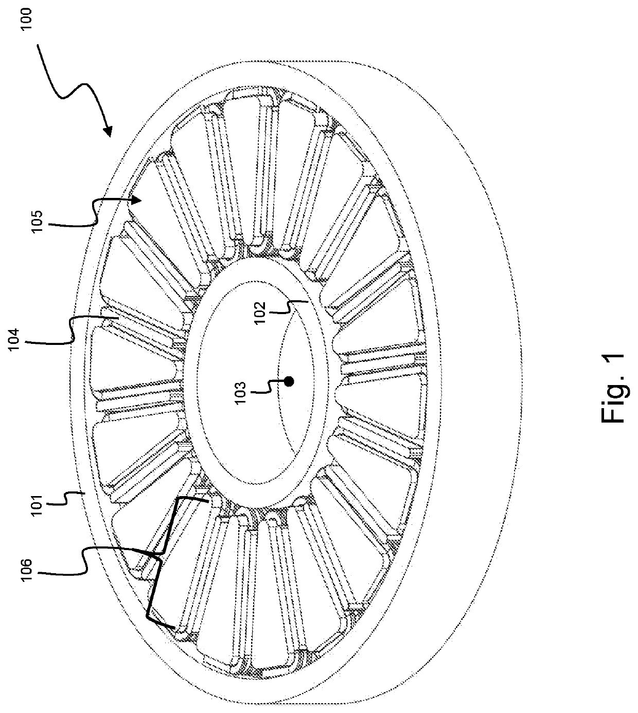
[0073]In FIG. 1 a stator for an axial flux machine is illustrated. The stator 100 comprises a central axis 103 which corresponds to the central axis of the axial flux machine when the stator 100 is mounted therein. The stator 100 further comprises an outer structure 101, an inner structure 102 and an intermediate structure 106. The intermediate structure 106 comprises a plurality of symmetrically arranged stator elements, such as stator element 105. The stator element 105 is further illustrated in FIG. 5. The stator element 105 comprises a ferromagnetic core 500 and turns 501-504 wound around the ferromagnetic core 500 thereby forming an electromagnet. The stator 100 further comprises guiding walls, such as guiding wall 104. In the embodiment of FIG. 1, the guiding walls 104 have an elongated shape, extending in radial direction. Moreover, a guiding wall 104 is positioned between each pair of adjacent stator elements 105.

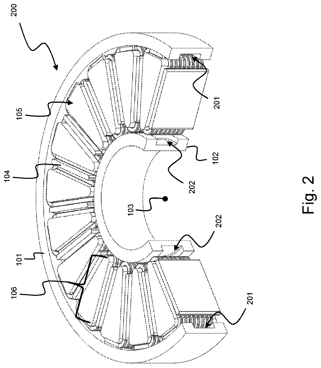
[0074]In FIG. 2 the stator is further illustrated with an open...


PUM


Abstract

A stator for an axial flux machine includes a central axis corresponding to the rotational axis of the axial flux machine; and ports for supplying and draining a cooling fluid; and an outer structure comprising an outer cooling channel to let the cooling fluid flow tangentially about the central axis; and the inner structure comprising an inner cooling channel to let the cooling fluid flow tangentially about the central axis; and the intermediate structure comprising symmetrically arranged stator members. A stator member has a ferromagnetic core, and a coil includes turns wound around the ferromagnetic core. The stator further has guiding walls configured to guide the cooling fluid between the outer and the inner cooling channels.

Description

FIELD OF THE INVENTION[0001]The present invention generally relates to the field of stators for axial flux machines. More specifically, the present invention relates to a cooling mechanism for cooling such a stator and a method thereof.BACKGROUND OF THE INVENTION[0002]An axial flux machine is a type of electrical machine known in the art under a variety of different terms. In particular, but not exclusively limited thereto, it is nominated as a yokeless and segmented armature (YASA) motor or generator, a yokeless axial flux machine, an axial air-gap electronic motor or generator, an axial flux permanent magnet machine, or merely an axial flux machine. These terms may indicate a particular embodiment of such a machine, yet, in the continuation of this text, the term axial flux machine will be used. Nevertheless, it is appreciated that the basic principles of an axial flux machine remain applicable.[0003]The basic principles are, broadly, that an axial flux machine comprises a disc- o...

Claims


Application Information

Patent Timeline
IPC IPC(8): H02K1/20H02K3/24H02K3/28
CPCH02K1/20H02K3/24H02K3/28H02K21/24H02K1/148H02K5/203H02K9/197
Inventor LEIJNEN, PETER
Owner MAGNAX BV
Why Eureka
Try Eureka