Package apparatus

a technology of packaging apparatus and packaging parts, which is applied in the direction of packaging, mechanical conveyors, conveyor parts, etc., can solve the problem of not increasing the processing speed, and achieve the effect of simplifying the configuration

Active Publication Date: 2012-10-23
ISHIDA CO LTD
View PDF13 Cites 13 Cited by
  • Summary
  • Abstract
  • Description
  • Claims
  • Application Information

AI Technical Summary

Benefits of technology

[0013]An object of the present invention is to provide a package apparatus capable of assuredly overlaying packaged objects on adjacent packaged objects so as to have the same orientation, and packing the packaged objects in boxes by using a simplified configuration.
[0042]The package apparatus according to the present invention is capable of assuredly overlaying the packaged objects on adjacent package objects so as to have the same orientation and packing the packaged objects in boxes by using a simplified configuration.

Problems solved by technology

However, almost half the contents of an object which is packaged by using a thin flexible material is air.
On the other hand, the object-packaged-in-bag raising aligning apparatus as disclosed in Patent Document 2 cannot increase a processing speed when the number of packaged objects is increased.

Method used


Image

  • Package apparatus
  • Package apparatus
  • Package apparatus

Examples


first embodiment

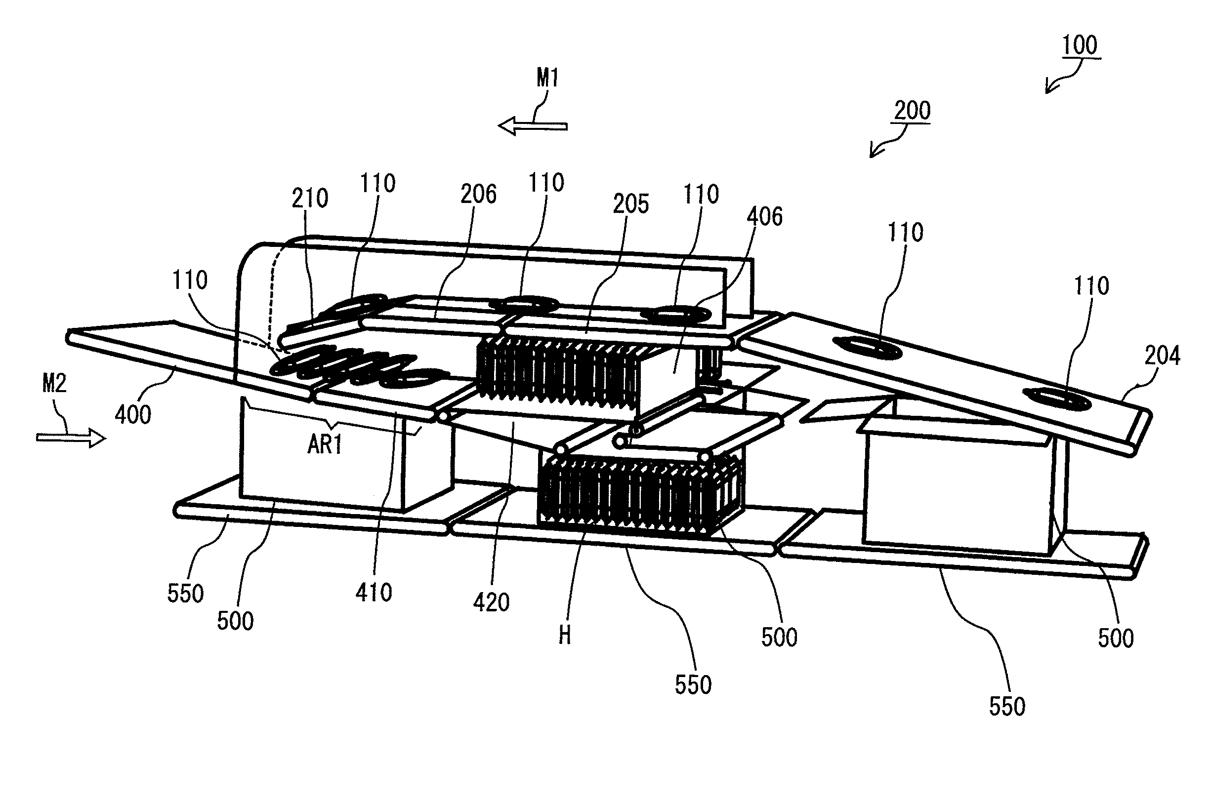
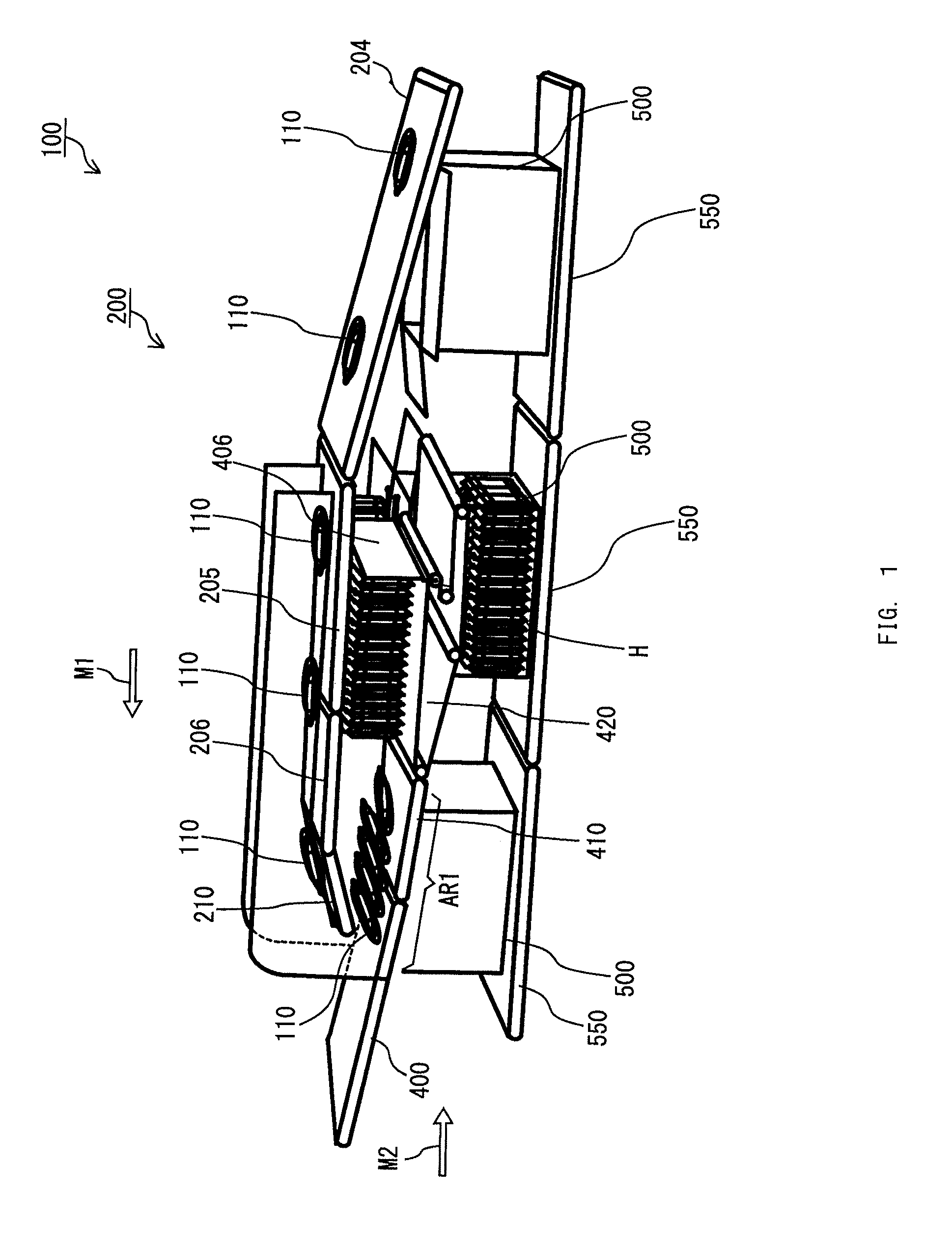
[0090]FIG. 1 is a schematic diagram illustrating an exemplary external appearance of a package apparatus 100 according to a first embodiment of the present invention.

[0091]The package apparatus 100 shown in FIG. 1 mainly includes: a first conveyance unit 200; a second conveyance unit 400; a third conveyance unit 410; an extendable conveyance unit 420; and a box conveyance unit 550. The first conveyance unit 200, the second conveyance unit 400, the third conveyance unit 410, and the extendable conveyance unit 420 are each formed as a conveyance structure having an endless belt conveyor. Further, except for the extendable conveyance unit 420, a conveyance surface of each belt conveyor is uneven, so that a frictional force is generated so as not to easily unbalance positions of packaged objects. Further, the extendable conveyance unit 420 is configured as a belt conveyor, such as a shuttle conveyor, in which the length of the conveyance surface is extendable.

[0092]The first conveyance ...

second embodiment

[0146]Hereinafter, a package apparatus 100 according to a second embodiment will be described. For the package apparatus 100 according to the second embodiment, components and operations different from those of the package apparatus 100 according to the first embodiment will be mainly described. FIG. 16 is a schematic diagram illustrating an exemplary external appearance of the package apparatus 100 according to the second embodiment.

[0147]The package apparatus 100 shown in FIG. 16 includes a first horizontal unit 205 as the first horizontal unit 205 and the second horizontal unit 206, and further includes a rotation prevention guide unit 600.

[0148]A first conveyance unit 200 shown in FIG. 16 moves a plurality of packaged objects in the direction indicated by an arrow M1. The first conveyance unit 200 includes the first horizontal unit 205 and a tilt unit 210, and the tilt unit 210 is provided immediately following the first horizontal unit 205.

[0149]Below the first conveyance unit ...

third embodiment

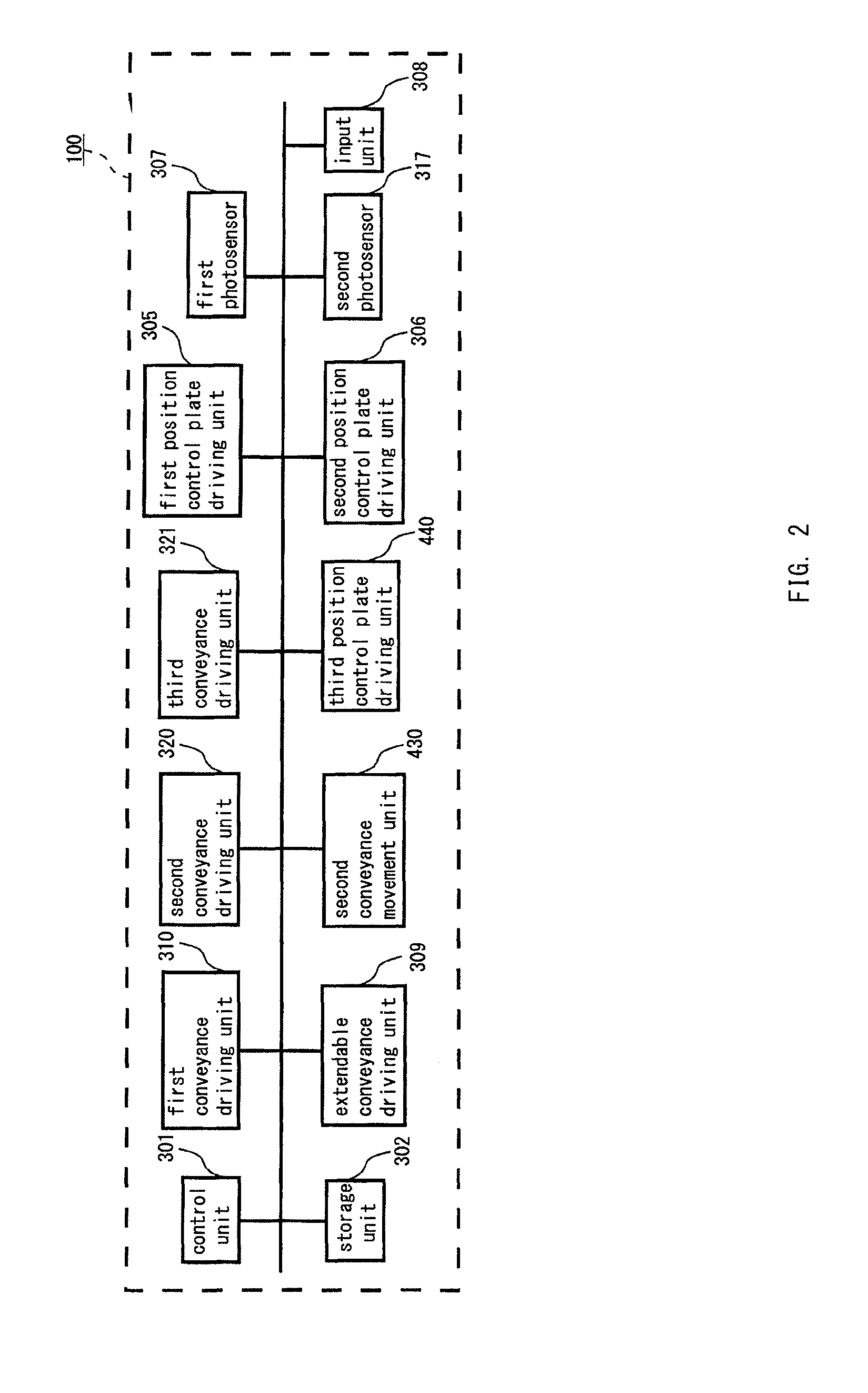
[0171]Hereinafter, a package apparatus 100 according to a third embodiment will be described. For the package apparatus 100 according to the third embodiment, components and operations which are different from those of the package apparatus 100 according to each of the first and the second embodiments will be mainly described. FIG. 24 is a schematic diagram illustrating an exemplary external appearance of the package apparatus 100 according to the third embodiment of the present invention. FIG. 25 is a schematic structure diagram illustrating main components of the package apparatus 100 according to the third embodiment.

[0172]As shown in FIG. 24, the package apparatus 100 may include second conveyance units 400 and 450 which are horizontally provided, without providing the extendable conveyance unit 420. As shown in FIG. 25, the package apparatus 100 may include: a control unit 301; a storage unit 302; a first position control plate driving unit 305; a second position control plate ...


PUM


Abstract

A package apparatus includes a first conveyance unit and a second conveyance unit. The first conveyance unit is configured and arranged to convey a plurality of packaged objects in a first conveying direction. The second conveyance unit is provided below the first conveyance unit and configured and arranged to convey the packaged objects in a second conveying direction generally opposite from the first conveying direction. The second conveyance unit is configured and arrange to overlay each of the packaged objects received from the first conveyance unit on an adjacent one of the packaged objects such that the packaged objects are generally oriented in the second conveying direction to form a group of the packaged objects that is conveyed in the second conveying direction on the second conveyance unit.

Description

CROSS-REFERENCE TO RELATED APPLICATIONS[0001]This application claims priority to Japanese Patent Application No. 2009-000032 filed on Jan. 5, 2009, Japanese Patent Application No. 2009-271405 filed on Nov. 30, 2009 and U.S. Provisional Application No. 61 / 231,514 filed on Aug. 5, 2009. The entire disclosures of Japanese Patent Application Nos. 2009-000032 and 2009-271405 and U.S. Provisional Application No. 61 / 231,514 are hereby incorporated herein by reference.BACKGROUND OF THE INVENTION[0002]1. Field of the Invention[0003]The present invention relates to a package apparatus used for packing packaged objects in boxes, and more particularly to a package apparatus for packing packaged objects in boxes.[0004]2. Description of the Background Art[0005]Conventionally, various package apparatuses for packing packaged objects in boxes are used. For example, an apparatus is known which suctions packaged objects by using a vacuum suction device, and moves the packaged objects, and packs the p...

Claims


Application Information

Patent Timeline
Patent Type & Authority Patents(United States)
IPC IPC(8): B65G47/24
CPCB65B5/061B65B35/44B65G47/647B65G47/082B65B35/56
Inventor IWASA, SEISAKUTAKAYAMA, MOTOKIARIMATSU, TATSUYAYOKOTA, YUJI
Owner ISHIDA CO LTD
Why Eureka
Try Eureka