Vehicle seat head rest with built-in electronic appliance

Active Publication Date: 2012-10-23
CONCEPT USA
View PDF25 Cites 16 Cited by
  • Summary
  • Abstract
  • Description
  • Claims
  • Application Information

AI Technical Summary

Benefits of technology

[0020]Another object of the present invention is to provide a vehicle seat head rest with a built-in electronic appliance, which dose not require to alter the original structural design of the vehicle seat, so as to minimize the manufacturing cost of the vehicle seat incorporating with the vehicle seat head rest of the present invention.
[0021]Another object of the present invention is to provide a vehicle seat head rest with a built-in ele

Problems solved by technology

Therefore, the driver cannot selectively switch the head rest from one car to another car.
Since the original manufactured head rest is mainly made for supporting the head of the driver, the LCD screen does not provide any rigid frame structure to support LCD screen.
In other words, the problem of the head rest is that the LCD screen may be damaged by the vibration and external shocks from the vehicle.
This happens because the supporting frame which holds the LCD screen provides a lot of freedom for the LCD screen to move around inside the head rest and thus damaging the electronic components of the LCD screen.
It will cost a lot for repairing the LCD screen due to the vast installation process.
Some models of the car may not even have an upgraded option for installing the LCD screen, DVD player, or any other electronic appliances for installing at the rear side of the vehicle seat head rest.
The installation structure not only damages the original head rest, but also has high installation cost for installing the LCD screen.
Firstly, the color and material of element for detachably mounting the LCD screen with the vehicle head rest will not match the color and texture of the origin

Method used


Image

  • Vehicle seat head rest with built-in electronic appliance
  • Vehicle seat head rest with built-in electronic appliance
  • Vehicle seat head rest with built-in electronic appliance

Examples


Embodiment Construction

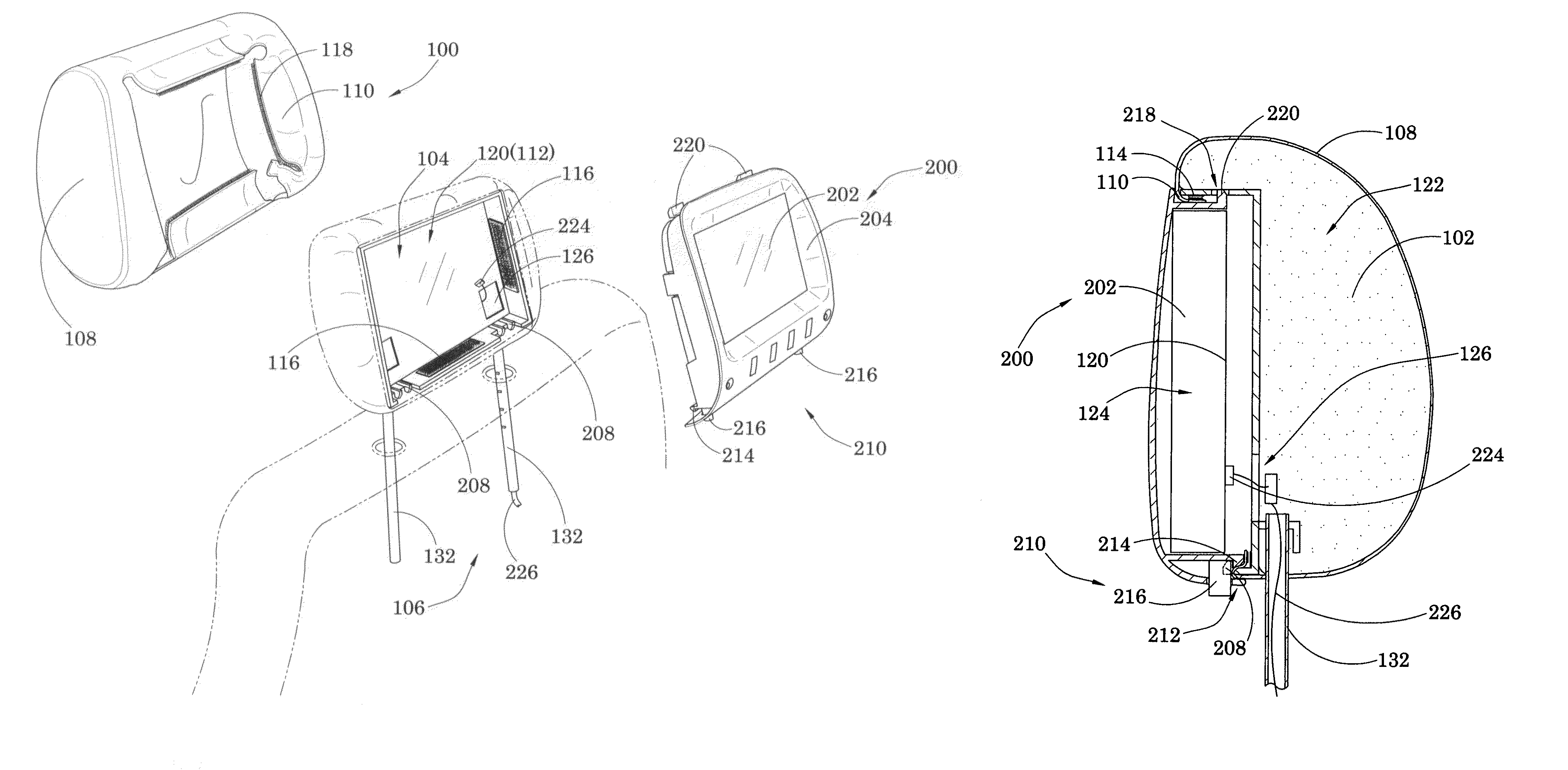
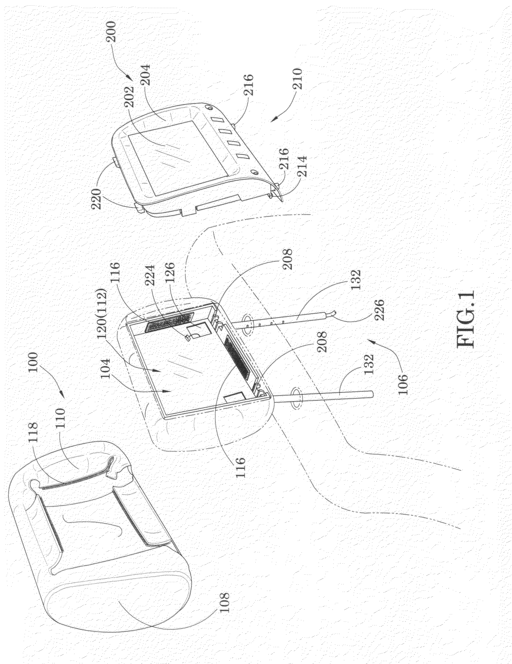
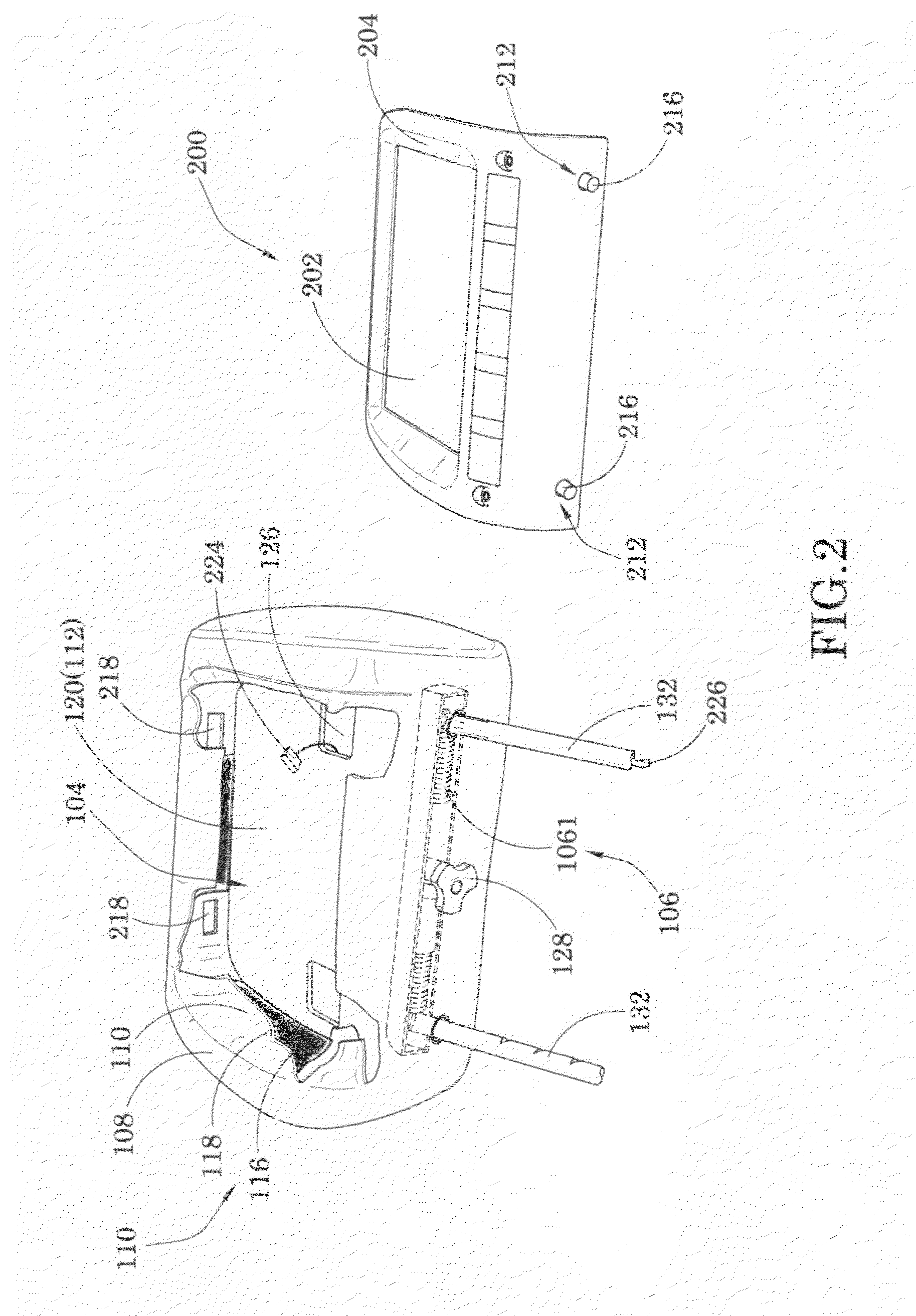
[0030]Referring to FIGS. 1 to 4 of the drawings, a vehicle seat head rest for mounting on a vehicle seat of a vehicle according to a preferred embodiment of the present invention is illustrated, wherein the vehicle seat head rest comprises a head pillow 100 and an electronic appliance 200.

[0031]The head pillow 100 comprises a pillow body 102 having a receiving cavity 104 indentedly formed at a rear side of the pillow body 102, a mounting arrangement 106 extended from the pillow body 102 to mount the head pillow 100 onto the vehicle seat of vehicle, and a replaceable skin 108 for detachably encasing the pillow body 102 at a position that a peripheral edge 110 of the replaceable skin 108 is folded at the rear side of the pillow body 102.

[0032]The electronic appliance 200 comprises a screen module 202, which is detachably mounted at the rear side of the pillow body 102 within the receiving cavity 104 thereof. In order to stably supporting the screen module 202 of the electronic applian...


PUM


Abstract

A vehicle seat head rest for mounting to a vehicle seat of a vehicle includes a head pillow and an electronic appliance including a screen module detachably mounted at the head pillow. The head pillow includes a pillow body having a receiving cavity formed at the rear side of the pillow body, a mounting arrangement for mounting to the vehicle seat, and a replaceable skin detachably encasing the pillow body at a position that a peripheral edge of the replaceable skin is folded at the rear side of the pillow body. The screen module is detachably mounted within the receiving cavity and is supported by an interior wall thereof. Thus, the peripheral edge of the replaceable skin is hidden after the screen module is detachably mounted at the rear side of the head pillow.

Description

BACKGROUND OF THE PRESENT INVENTION[0001]1. Field of Invention[0002]The present invention relates to a vehicle seat head rest, and more particularly to a vehicle seat head rest with a built-in electronic appliance, which provides the electronic appliance being detachably mounted at the rear side of the head rest and the replaceable skin to be interchanged for matching with the material of the vehicle seat.[0003]2. Description of Related Arts[0004]A conventional head rest for car seat comprises a head pillow and two parallel supporting rods downwardly extended from the head pillow to slidably engage with two retention slots of the car seat. Accordingly, as different car models have different sizes of car seat, a specific dimensioned head rest might be tailor-made for the specific car seat. In other words, the distance between the two supporting rods of the head rest must match with a distance between the two retention slots of the car seat. Therefore, the driver cannot selectively sw...

Claims


Application Information

Patent Timeline
IPC IPC(8): A47C7/62B60N2/806B60N2/879B60N2/90
CPCB60N2/4876B60N2/879B60N2/806
Inventor LIU, EDWARD
Owner CONCEPT USA
Why Eureka
Try Eureka